

Project Overview
Build a Line Follower Robot with Arduino Uno, IR line sensors, and the L298N: Build a two-motor robot car that follows a black tape line by reading two infrared sensors and driving the motors through an L298N H-bridge.
This is a classic robotics starter project: sense, decide, drive, repeated many times per second using simple if-statements.
- Time: 2-3 hours
- Skill level: Beginner
- What you will build: An autonomous robot that follows a black tape track using two IR sensors and an L298N motor driver.

Parts List
From ShillehTek
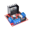
- L298N Motor Driver Board - the H-bridge that lets a 5V Arduino control battery-powered DC motors forward and reverse
- Arduino Uno R3 - the microcontroller that reads the sensors and drives the motor control pins
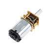
- N20 Micro Metal Gear Motors (12V, 100RPM) - compact geared drive motors (or use TT motors from many chassis kits)
- Dupont Jumper Wires - wiring between the Uno, sensors, and motor driver
- 400-Point Breadboard - quick prototyping for sensor and control wiring
External
- 2WD robot chassis with wheels + caster
- 2 x IR line-tracking sensor modules (TCRT5000-style, digital output)
- Battery pack (6-12V) and black electrical tape for the track
Note: IR line sensors work by reflection. White surfaces reflect infrared (module output changes), while black tape absorbs it. Most modules include a potentiometer to tune sensitivity; adjust it so the onboard LED flips right at the tape edge.
Step-by-Step Guide
Step 1 - Assemble the Chassis
Goal: Build a stable rolling platform and place the sensors correctly.
What to do: Mount the two gear motors and wheels, add the caster at the front, and mount the battery pack low and centered. Install the two IR sensors at the front edge facing down, about 10 to 15 mm above the floor. Space the sensors slightly wider than your tape line so the line runs between them when the robot is centered.
Expected result: A chassis with two downward-facing sensors positioned to straddle the tape line.
Step 2 - Wire the Electronics
Goal: Connect sensor outputs to the Arduino and motor control pins to the L298N.
What to do: Wire the IR sensors: VCC to 5V, GND to GND, left OUT to A0, right OUT to A1. Wire the L298N control pins: IN1 to D8, IN2 to D9 (left motor), IN3 to D10, IN4 to D11 (right motor). Keep ENA/ENB jumpered high for full speed, or wire ENA/ENB to PWM pins D5/D6 if you want speed control.
Power: connect battery positive to L298N VIN, and ensure all grounds are common. The L298N onboard 5V regulator can feed the Arduino Uno 5V pin.
Expected result: One battery powers the system, and the motors respond when you toggle the IN pins.
Step 3 - Upload the Follow Logic
Goal: Implement a simple truth table to steer using two sensors.
What to do: Use these rules: both sensors see white, drive forward. Left sensor sees the line, pivot left. Right sensor sees the line, pivot right. Both sensors see the line (crossing or end), stop. Upload this Arduino sketch:
Code:
#define IR_L A0
#define IR_R A1
#define IN1 8
#define IN2 9
#define IN3 10
#define IN4 11

// most TCRT5000 modules read LOW on the black line
#define ON_LINE LOW

void drive(bool l1, bool l2, bool r1, bool r2) {
  digitalWrite(IN1, l1); digitalWrite(IN2, l2);
  digitalWrite(IN3, r1); digitalWrite(IN4, r2);
}

void setup() {
  pinMode(IR_L, INPUT);  pinMode(IR_R, INPUT);
  pinMode(IN1, OUTPUT);  pinMode(IN2, OUTPUT);
  pinMode(IN3, OUTPUT);  pinMode(IN4, OUTPUT);
}

void loop() {
  bool leftOnLine  = (digitalRead(IR_L) == ON_LINE);
  bool rightOnLine = (digitalRead(IR_R) == ON_LINE);

  if (!leftOnLine && !rightOnLine)      drive(HIGH, LOW, HIGH, LOW);  // forward
  else if (leftOnLine && !rightOnLine)  drive(LOW,  LOW, HIGH, LOW);  // turn left
  else if (!leftOnLine && rightOnLine)  drive(HIGH, LOW, LOW,  LOW);  // turn right
  else                                  drive(LOW,  LOW, LOW,  LOW);  // stop
}
Expected result: When placed on a tape track, the robot follows the line and corrects itself through curves.
Step 4 - Tune It
Goal: Improve tracking smoothness and reduce wobble or overshoot.
What to do: Adjust three main variables: sensor height (closer gives sharper edge detection), sensor spacing (wider can correct earlier but may wobble more), and speed (for speed control, wire ENA/ENB to PWM and use analogWrite around 140 to 180; full speed often overshoots corners).
If the robot veers off immediately, your modules may read HIGH on the line instead of LOW. Change ON_LINE to match your sensor behavior.
Expected result: Stable laps around a full loop without frequent dropouts.
Step 5 - Level Up
Goal: Extend the same sense-think-act loop into more advanced behaviors.
What to do: Consider upgrading to a 5-channel sensor array for smoother steering, adding an ultrasonic sensor to stop for obstacles, or adding a crossing counter to navigate a line maze. The overall control structure stays the same.
Expected result: A solid base platform for more autonomous driving experiments.
Conclusion
You built an Arduino Uno line follower robot using two IR line sensors and an L298N motor driver, controlled by a simple decision table. This project teaches the core loop behind many robots: read sensors, decide, and drive motors.
Want the exact parts used in this build? Grab them from ShillehTek.com. If you want help customizing this project or building something for your product, check out our IoT consulting services.
Attribution: This tutorial references the original guide by sairushan on Hackster.io.





.png?v=25000753014097803521791168436)

.png?v=68677308723310773341791168436)