

Project Overview
Arduino Uno keyless door lock with a 4x4 keypad and LCD1602: You will build a password-based lock where a 4-digit code entered on a 4x4 keypad is shown as masked characters on a 16x2 LCD, then a relay triggers a solenoid lock. The password is stored in EEPROM so it survives power loss, and it can be changed from the keypad.
- Time: 1 to 2 hours
- Skill level: Intermediate
- What you will build: A complete password entry system with LCD prompts, EEPROM-stored code, and a relay-controlled solenoid lock.

Parts List
From ShillehTek
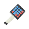
- 4x4 Membrane Matrix Keypad - for entering the 4-digit access code
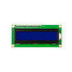
- LCD1602 16x2 Display - shows prompts and access status
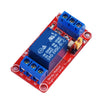
- 1-Channel 5V Relay Module - switches power to the solenoid lock
- Arduino Uno R3 - runs the keypad, LCD, EEPROM logic, and relay control
- Resistor Kit - use 220Ω for the LCD backlight
- 400-Point Breadboard - quick prototyping before mounting
- Dupont Jumper Wires - connects the keypad, LCD, and relay to the Uno
External
- 12V DC solenoid lock + 12V supply (or 9V battery for bench testing)
- 10kΩ potentiometer for LCD contrast
Note: The relay isolates the Arduino from the solenoid's 12V coil. The Uno only switches the relay's 5V signal pin. Never drive a solenoid directly from a GPIO.
Step-by-Step Guide
Step 1 - Wire the keypad, LCD, and relay
Goal: Connect three subsystems to one Arduino Uno.
What to do: Wire keypad rows to A0 to A3, and keypad columns to A4, A5, D3, and D2. Wire the LCD1602 in 4-bit mode on D4 to D9 (use a contrast potentiometer on V0, and a 220Ω resistor for the backlight). Wire the relay signal pin to D10, with relay VCC and GND to 5V and GND. Switch the solenoid's 12V supply through the relay COM and NO terminals.

Expected result: The keypad, LCD, and relay are fully wired and powered.
Step 2 - Understand the EEPROM password logic
Goal: Know what the sketch does before uploading.
What to do: The password (default 1234) is stored in EEPROM (non-volatile memory), so unplugging the system does not reset the code. On boot, the LCD prompts Enter Password:. Each keypress prints a *. After 4 digits, the input is compared to the EEPROM-stored password. If it matches, the relay energizes and the lock opens for a few seconds; if it does not match, the LCD shows Access Denied. Pressing # enters the password-change routine, which requires the current code before accepting a new one.
Expected result: You can trace the behavior for entry, denial, unlock, and password change.
Step 3 - Install libraries and upload the sketch
Goal: Program the Arduino Uno to read the keypad, update the LCD, and control the relay.
What to do: Install the Keypad library (Mark Stanley/Alexander Brevig). LiquidCrystal and EEPROM are included with the Arduino IDE. Upload the sketch below (this core example demonstrates the EEPROM check and relay unlock behavior).
Code:
#include <Keypad.h>
#include <LiquidCrystal.h>
#include <EEPROM.h>

LiquidCrystal lcd(9, 8, 7, 6, 5, 4);
const int relayPin = 10;

const byte ROWS = 4, COLS = 4;
char keys[ROWS][COLS] = {
  {'1','2','3','A'}, {'4','5','6','B'},
  {'7','8','9','C'}, {'*','0','#','D'}
};
byte rowPins[ROWS] = {A0, A1, A2, A3};
byte colPins[COLS] = {A4, A5, 3, 2};
Keypad keypad = Keypad(makeKeymap(keys), rowPins, colPins, ROWS, COLS);

char entered[5];
byte pos = 0;

bool checkPassword() {
  for (byte i = 0; i < 4; i++)
    if (entered[i] != (char)EEPROM.read(i)) return false;
  return true;
}

void setup() {
  lcd.begin(16, 2);
  pinMode(relayPin, OUTPUT);
  if (EEPROM.read(0) == 255) {          // first boot: store default 1234
    const char def[4] = {'1','2','3','4'};
    for (byte i = 0; i < 4; i++) EEPROM.write(i, def[i]);
  }
  lcd.print("Enter Password:");
}

void loop() {
  char key = keypad.getKey();
  if (!key) return;

  entered[pos++] = key;
  lcd.setCursor(pos - 1, 1);
  lcd.print('*');

  if (pos == 4) {
    lcd.clear();
    if (checkPassword()) {
      lcd.print("Access Granted");
      digitalWrite(relayPin, HIGH);     // fire the lock
      delay(5000);
      digitalWrite(relayPin, LOW);
    } else {
      lcd.print("Access Denied");
      delay(2000);
    }
    pos = 0;
    lcd.clear();
    lcd.print("Enter Password:");
  }
}
Expected result: The correct code unlocks for 5 seconds; the wrong code is denied. (The full version adds the # password-change routine using the same EEPROM reads and writes with an extra menu state.)
Step 4 - Test on the bench, then mount on a door
Goal: Validate every path before installing hardware.
What to do: Bench-test the correct code, wrong code, and power-cycle behavior (the password should survive). If you are using a version with code change, test changing the code from the keypad. Then mount the solenoid in the door frame, with the keypad and LCD outside. Mount the Arduino, relay, and power supply on the secure side of the door.
Expected result: A working keyless entry system for a door, cabinet, or drop-box.
Step 5 - Harden and extend the design
Goal: Turn the basic lock into a more robust access-control platform.
What to do: Add features such as lockout after 3 wrong attempts, a buzzer chirp per keypress, or longer codes (increase array sizes). You can also add an RFID reader alongside the keypad for two-factor entry. The relay output can drive other loads like a garage-door opener or an electric strike.
Expected result: A stronger base design that you can customize for real installations.
Conclusion
This Arduino Uno project combines a 4x4 keypad, LCD1602 feedback, EEPROM-stored password checking, and a relay output to control a solenoid door lock. The EEPROM approach is especially useful any time you need settings that persist after power loss.
Want the exact parts used in this build? Grab them from ShillehTek.com. If you want help customizing this project or building something for your product, check out our IoT consulting services.
Attribution: All photos and images in this tutorial are credited to Ali Hamza (DIY Hacking) on Hackster.io. The original guide served as the reference for this ShillehTek version.






.png?v=25000753014097803521791168436)

.png?v=68677308723310773341791168436)


