

Project Overview
Arduino SX1278 LoRa (Ra-02) point-to-point link: In this project, you build a complete 433 MHz point-to-point LoRa connection where one Arduino transmits numbered packets through an Ra-02 SX1278 module and a second Arduino receives them, blinks an LED, and shows the message plus signal strength (RSSI) on an SSD1306 OLED.
LoRa is a wireless modulation scheme built on Chirp Spread Spectrum. It trades bandwidth for excellent range and penetration at low power, which makes it ideal for long-distance sensor links without WiFi, gateways, or subscriptions.
- Time: 1 to 2 hours
- Skill level: Intermediate
- What you will build: A working 433 MHz LoRa transmitter/receiver pair with an OLED status display.

Parts List
From ShillehTek
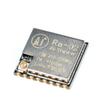
- Ra-02 SX1278 LoRa 433MHz Wireless Transceiver Module - you need two
- Arduino Nano V3 x 2 (any UNO-compatible boards work)
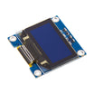
- SSD1306 0.96" I2C OLED Display - for the receiver readout
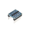
- Logic Level Converter - recommended between a 5V Arduino's SPI pins and the 3.3V module
- Jumper wires and breadboards
External
- 433 MHz antennas (never transmit without an antenna attached - it can damage the module)
- One LED for the receive indicator
Note: The Ra-02 is a 3.3V device. Power it from 3.3V only. 5V on VCC (or hard-driven 5V logic lines) can permanently damage it.
Step-by-Step Guide
Step 1 - Understand LoRa in Two Minutes
Goal: Know what makes this radio special.
What to do: LoRa's chirp spread spectrum encodes data in frequency sweeps, which lets receivers pull packets out of noise far below levels where WiFi typically fails. This is what enables long-range links. LoRaWAN adds a network protocol for gateway-based deployments, but for module-to-module links like this one, the Arduino LoRa library (or RadioHead) can communicate directly between two SX1278 radios with no infrastructure.
Expected result: You understand this build is raw point-to-point LoRa, not LoRaWAN.
Step 2 - Wire the Transmitter
Goal: Connect the first Ra-02 over SPI.
What to do: The module communicates over SPI. Use the standard hookup for the Arduino LoRa library:
Ra-02 3.3V -> 3.3V     Ra-02 GND -> GND
NSS  -> D10    MOSI -> D11    MISO -> D12
SCK  -> D13    RST  -> D9     DIO0 -> D2
Antenna -> ANT (always attached!)
Expected result: The transmitter is wired correctly and the antenna is attached.
Step 3 - Upload the Transmitter Sketch
Goal: Broadcast a packet every five seconds.
What to do: Install the "LoRa" library by Sandeep Mistry from the Arduino Library Manager, then upload this sketch:
#include <SPI.h>
#include <LoRa.h>

int counter = 0;

void setup() {
  Serial.begin(9600);
  while (!Serial);
  Serial.println("LoRa Sender");
  if (!LoRa.begin(433E6)) {
    Serial.println("Starting LoRa failed!");
    while (1);
  }
  LoRa.setTxPower(20);
}

void loop() {
  Serial.print("Sending packet: ");
  Serial.println(counter);
  LoRa.beginPacket();
  LoRa.print("hello ");
  LoRa.print(counter);
  LoRa.endPacket();
  counter++;
  delay(5000);
}
Expected result: In the Serial Monitor you see: "Sending packet: 0, 1, 2..." every five seconds.
Step 4 - Wire the Receiver
Goal: Connect the second Ra-02 plus the OLED and LED.
What to do: Duplicate the SPI wiring from Step 2 on the second Arduino. Then add the SSD1306 OLED on I2C (SDA to A4, SCL to A5, address 0x3C) and wire an LED to pin 3 as a receive indicator.

Expected result: The receiver hardware is complete: LoRa module, OLED, and LED are connected.
Step 5 - Upload the Receiver Sketch
Goal: Receive packets and display them with RSSI.
What to do: Install Adafruit GFX and Adafruit SSD1306 from the Arduino Library Manager, then upload this sketch:
#include <Wire.h>
#include <Adafruit_GFX.h>
#include <Adafruit_SSD1306.h>
#include <SPI.h>
#include <LoRa.h>

#define SCREEN_WIDTH 128
#define SCREEN_HEIGHT 64
#define OLED_RESET -1

Adafruit_SSD1306 display(SCREEN_WIDTH, SCREEN_HEIGHT, &Wire, OLED_RESET);

String inString = "";
String myMessage = "";
int led = 3;

void setup() {
  Serial.begin(9600);
  if (!display.begin(SSD1306_SWITCHCAPVCC, 0x3C)) {
    Serial.println(F("SSD1306 allocation failed"));
    for (;;);
  }
  delay(2000);
  display.clearDisplay();
  display.display();
  while (!Serial);
  Serial.println("LoRa Receiver");
  display.clearDisplay();
  display.setTextSize(1);
  display.setTextColor(WHITE);
  display.setCursor(20, 30);
  display.println("LoRa Receiver");
  display.display();
  if (!LoRa.begin(433E6)) {
    Serial.println("Starting LoRa failed!");
    while (1);
  }
  pinMode(led, OUTPUT);
}

void loop() {
  String message = "";
  int packetSize = LoRa.parsePacket();
  if (packetSize) {
    Serial.print("Received packet '");
    digitalWrite(led, HIGH);
    delay(1000);
    display.clearDisplay();
    display.setTextSize(1);
    display.setTextColor(WHITE);
    display.setCursor(0, 10);
    display.println("Received packet - ");
    display.display();
    Serial.println(packetSize);
    while (LoRa.available()) {
      message += (char)LoRa.read();
    }
    display.setTextSize(1);
    display.setTextColor(WHITE);
    display.setCursor(20, 30);
    display.println(message);
    display.display();
    Serial.print(message);
    Serial.print("' with RSSI ");
    Serial.println(LoRa.packetRssi());
    digitalWrite(led, LOW);
  }
}
Expected result: The OLED shows "LoRa Receiver" on boot, then each incoming "hello N" message. The Serial Monitor prints RSSI for each received packet.
Step 6 - Test the Link and Range
Goal: Verify communication, then evaluate real-world range.
What to do: Power both boards. Every five seconds the LED blinks on the receiver and the OLED updates. Move the devices farther apart and watch how RSSI changes. Values around -50 dBm typically indicate close range; the link can still work as RSSI approaches about -120 dBm depending on environment and antennas.
Expected result: Reliable packet reception well beyond typical WiFi range, with RSSI providing a signal-strength reference.
Conclusion
You built a complete 433 MHz point-to-point LoRa link using two Ra-02 SX1278 modules and Arduino boards: SPI wiring, a transmitter that sends numbered packets, and a receiver that shows messages and RSSI on an SSD1306 OLED while blinking an LED.
Want the exact parts used in this build? Grab them from ShillehTek.com. If you want help customizing this project or building something for your product, check out our IoT consulting services.





.png?v=25000753014097803521791168436)

.png?v=68677308723310773341791168436)


