

Project Overview
Arduino + PN532 NFC/RFID module: In this build, you will wire a PN532 NFC/RFID reader-writer to an Arduino over UART, display read/write results on a 1602 LCD, and (optionally) store credits directly on a MIFARE tag as an electronic wallet.
The PN532 is one of the most capable hobbyist NFC modules. It reads and writes 13.56 MHz MIFARE tags and supports UART, I2C, or SPI. This guide uses the Arduino serial port with a simple two-resistor voltage divider instead of a level shifter, then explores packed-BCD value storage similar to payment-style systems.
- Time: 1 to 2 hours
- Skill level: Intermediate
- What you will build: A PN532 tag reader-writer with an LCD readout, plus an optional tap-to-pay style credit system stored on the tag.

Parts List
From ShillehTek
- PN532 NFC RFID Reader/Writer Module V3 - the NFC/RFID reader-writer used for all tag operations
- Arduino Nano V3 - or any Arduino UNO-compatible board to run the sketches and drive the LCD
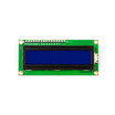
- LCD1602 16x2 Display Module - displays read/write data and wallet values
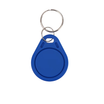
- 13.56MHz RFID Smart Card (S50 1K) and S50 key fob - tags to read, write, and store credits (wallet version)
- Metal Film Resistor Kit - used to build the two-resistor UART voltage divider
- 830-Point Breadboard and jumper wires - prototyping and wiring
External
- 10K potentiometer - LCD contrast adjustment
- Two small switches - only needed for the wallet version (tag initialize and add credits)
Note: Set the PN532 interface DIP switches to UART/HSU mode for this build.
Step-by-Step Guide
Step 1 - Wire It (and learn the two-resistor trick)
Goal: Connect the PN532, LCD, and Arduino without a level shifter.
What to do: Wire the PN532 to the Arduino UART and wire the 1602 LCD in classic 4-bit mode using the schematic below.
The key detail is voltage levels: the PN532 module VCC can accept 5V, but the PN532 chip uses 3.3V logic. Put a two-resistor voltage divider on the Arduino TX line before it reaches the PN532 RXD input. No conversion is needed from the PN532 TX back to the Arduino RX because 3.3V is read as HIGH by the Arduino.
The two switches shown are optional and only apply to the wallet version (tag initialize and add credits).

Expected result: A safely level-matched serial link to the PN532.
Step 2 - Run the basic read/write demo
Goal: Prove you can read and write tag memory.
What to do: Use the basic demo sketch from the original PN532.zip referenced by the credited page below. The demo authenticates a MIFARE tag, writes an arbitrary data pattern to a block, reads it back, and modifies the pattern each pass so every scan confirms both writing and reading on the LCD.
Expected result: Tap a card and see data round-trip to and from tag memory on the LCD.
Step 3 - Understand the electronic wallet version
Goal: Store credits on the tag like a transit card.
What to do: Load the wallet sketch. It initializes a tag with a credit value of zero, then increments or decrements it by amounts defined at the top of the code.
The important detail is data format: values are stored on the card in packed BCD. For example, hex 0x12 represents decimal twelve. This convention is common in payment-style systems because values remain human-auditable in memory dumps.
Expected result: You can explain why 0x12 is twelve, not eighteen, in this wallet format.
Step 4 - Appreciate the BCD math (DAA/DAS)
Goal: Understand why the code uses decimal adjust routines.
What to do: When you add or subtract packed-BCD values using normal binary arithmetic, digits can become invalid unless the result is corrected. Some CPUs provide Decimal Adjust after Add/Subtract (DAA/DAS) in hardware, but the AVR used by many Arduino boards does not. The sketch implements DAA in software and adds a hand-written DAS so the stored credits stay correct in decimal.
Expected result: Credits add and subtract cleanly in decimal and remain stored on the tag itself.
Step 5 - Make it yours
Goal: Extend the basics into a real system.
What to do: Once read/write and value storage work, you can adapt the idea to projects like arcade tokens, maker-space door credits, coffee-club punch cards, or access control. Pair the module with S50 cards and fobs and each tag can act like a tiny database.
Expected result: A working NFC foundation you can build into your own products.
Attribution: This build is based on the original reference and code credited at Instructables.
Conclusion
You wired a PN532 NFC/RFID module to an Arduino over serial using a two-resistor voltage divider, validated MIFARE tag read/write with a 1602 LCD, and explored an optional packed-BCD electronic wallet with software DAA/DAS.
Want the exact parts used in this build? Grab them from ShillehTek.com. If you want help customizing this project or building something for your product, check out our IoT consulting services.







.png?v=25000753014097803521791168436)

.png?v=68677308723310773341791168436)


