

Project Overview
Arduino 10K NTC Thermistor LCD Thermometer: Build an Arduino Nano (or UNO-compatible) thermometer using a 10K NTC thermistor, then display live temperature in C and F on a 16x2 LCD with an over-temperature LED and buzzer alarm.
A thermistor is one of the most affordable temperature sensors: its resistance drops as temperature rises. With a simple 10K/10K voltage divider into an Arduino analog pin and the Steinhart-Hart equation, you can get surprisingly accurate readings.
- Time: About 1 hour
- Skill level: Beginner
- What you will build: An LCD thermometer with a high-temperature alarm, built around a 10K NTC thermistor.

Parts List
From ShillehTek
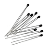
- 10K NTC Thermistor (MF52-103) - the temperature sensor used in the voltage divider.
- Arduino Nano V3 - reads the analog divider voltage and drives the LCD, LEDs, and buzzer (or any Arduino UNO-compatible board).
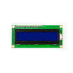
- LCD1602 16x2 Display Module - displays temperature in C and F.
- Metal Film Resistor Kit - provides the 10K fixed divider resistor and current-limiting resistors for the LEDs.
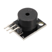
- KY-006 Passive Piezo Buzzer - audible over-temperature alarm output.
- 830-Point Breadboard and jumper wires - for quick prototyping and wiring.
External
- Green and red LEDs - visual normal and alarm indicators.
- 10K potentiometer - LCD contrast control (to LCD V0).
- 9V battery (optional) - standalone power option.
Note: This build assumes a 5V Arduino and a 10K fixed resistor paired with a 10K NTC thermistor in a voltage divider feeding A0.

Step-by-Step Guide
Step 1 - Understand the Voltage Divider
Goal: Know how a resistor becomes a thermometer.
What to do: Build the sensing circuit using two components in series between 5V and GND: the thermistor on top, a fixed 10K resistor on the bottom, with the junction feeding analog pin A0.
//              Analog pin A0
//                    |
// 5V |-----/\/\/\----+----/\/\/\-----| GND
//           ^                ^
//    10K thermistor     10K resistor
As temperature rises, the NTC resistance drops, the divider voltage shifts, and the ADC reading changes. The code converts that change into degrees.
Expected result: You can explain why A0 voltage tracks temperature.
Step 2 - Wire the Full Circuit
Goal: Divider, LCD, LEDs, and buzzer connected.
What to do: Wire the thermistor divider into A0. Connect the LCD in 4-bit parallel mode with RS to D2, E to D3, and D4 to D7 to Arduino pins D4 to D7 (use the contrast potentiometer on LCD V0). Wire a green LED to D8 and a red LED to D9 through series resistors. Wire the buzzer to D13.


Expected result: A complete breadboard circuit matching the schematic.
Step 3 - Upload the Steinhart-Hart Sketch
Goal: Convert resistance to accurate degrees.
What to do: Upload the sketch below (by Muhammad Ansar / embeddedlab786). It averages 50 ADC samples for stability, computes thermistor resistance, then applies the Steinhart-Hart equation with standard 10K NTC coefficients. Above 100 F, the red LED and buzzer activate; otherwise the green LED stays on.
Code:
#include <LiquidCrystal.h>
LiquidCrystal lcd(2, 3, 4, 5, 6, 7); // Arduino pins to LCD

#define ThermistorPin A0
long ADC_Value;
float R1 = 10000; // fixed divider resistor
float logR2, R2, T;

// Steinhart-Hart coefficients for a 10K NTC
float c1 = 0.001129148, c2 = 0.000234125, c3 = 0.0000000876741;
float temp_c, temp_f;

#define G_led 8
#define R_led 9
#define buzzer 13

void setup() {
  pinMode(ThermistorPin, INPUT);
  pinMode(R_led, OUTPUT);
  pinMode(G_led, OUTPUT);
  pinMode(buzzer, OUTPUT);

  lcd.begin(16, 2);
  lcd.clear();
  lcd.setCursor(0, 0);
  lcd.print("   Welcome To   ");
  lcd.setCursor(0, 1);
  lcd.print("Temperature NTC");
  delay(2000);
  lcd.clear();
}

void loop() {
  ADC_Value = 0;
  for (int i = 0; i < 50; i++) {   // average 50 samples
    ADC_Value = ADC_Value + analogRead(ThermistorPin);
    delay(1);
  }
  ADC_Value = ADC_Value / 50;

  R2 = R1 * (1023.0 / (float)ADC_Value - 1.0); // thermistor resistance
  logR2 = log(R2);
  temp_c = (1.0 / (c1 + c2*logR2 + c3*logR2*logR2*logR2)); // Kelvin
  temp_c = temp_c - 273.15;                    // to Celsius
  temp_f = (temp_c * 9.0) / 5.0 + 32.0;        // to Fahrenheit

  lcd.setCursor(0, 0);
  lcd.print("  Temperature   ");
  lcd.setCursor(0, 1);
  lcd.print(temp_c, 1);
  lcd.write(0xdf); // degree symbol
  lcd.print("C  ");
  lcd.setCursor(9, 1);
  lcd.print(temp_f, 1);
  lcd.write(0xdf);
  lcd.print("F  ");

  if (temp_f > 100) {
    digitalWrite(buzzer, HIGH);
    digitalWrite(G_led, LOW);
    digitalWrite(R_led, HIGH);
    delay(300);
  } else {
    digitalWrite(G_led, HIGH);
    digitalWrite(R_led, LOW);
  }

  digitalWrite(buzzer, LOW);
  delay(500);
}
Expected result: A welcome screen, then live C and F readings updating about twice per second.
Step 4 - Test the Alarm
Goal: Verify the whole chain.
What to do: Pinch the thermistor between your fingers and watch the temperature climb. Warm it past 100 F (37.8 C) and the red LED should light with the buzzer chirping. Let it cool and the green LED returns. Adjust the temp_f > 100 threshold for your application.

Expected result: Accurate readings and a working over-temperature alarm.
Conclusion
You turned a 10K NTC thermistor into a calibrated Arduino LCD thermometer using a simple divider and the Steinhart-Hart equation, complete with visual and audible alarms. This same pattern is useful for enclosures, incubators, aquariums, and other low-cost temperature monitoring projects.
Reference credit: photos and original guide credited to Hackster.io and Muhammad Ansar (embeddedlab786).
Want the exact parts used in this build? Grab them from ShillehTek.com. If you want help customizing this project or building something for your product, check out our IoT consulting services.






.png?v=25000753014097803521791168436)

.png?v=68677308723310773341791168436)


