

Project Overview
Breakout on an 8x8 WS2812 Matrix: Build a two-button Breakout arcade game on an Arduino Nano using a WS2812 8x8 RGB LED matrix, complete with bricks, lives, increasing ball speed, and buzzer sound effects.
Sixty-four RGB pixels are enough for a real game. This Breakout has three rows of coloured bricks, a three-pixel paddle you steer with two buttons, a ball that speeds up as you clear the wall, three lives, a buzzer for every bounce, and a win animation. Behind it is a clean game loop with non-blocking timers, a serpentine XY() mapping, and collision checks in the right order that you can reuse for Snake, Pong or Tetris on the same matrix.
- Time: ~45 minutes
- Skill level: Intermediate
- What you will build: A complete, replayable Breakout with 24 bricks, edge "english" on the paddle, increasing speed and sound effects, using FastLED.

Parts List
From ShillehTek
- Arduino Nano V3.0 Pre-Soldered - runs the game loop and reads the buttons
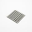
- WS2812 8x8 LED Matrix - displays the bricks, paddle, and ball
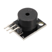
- KY-006 Passive Buzzer - sound effects for bounces and events
- Tactile Button Kit - two inputs for left and right control
- Resistor Kit - 330Ω in series with the WS2812 data line
- Electrolytic Capacitor Kit - 220 µF across the matrix supply to reduce power spikes
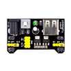
- MB102 Breadboard Power Supply - optional, for full-brightness play
- 830-Point Breadboard - mounting and wiring the build
- Dupont Jumper Wires - connections between Nano, matrix, buttons, and buzzer
External
- None
Note: 64 WS2812 pixels at full white draw up to 3.8 A. The sketch caps brightness at 40/255 so a USB port copes, but for a bright, boxed-up game feed the matrix from the MB102 or a 5 V 3 A supply, and always share GND with the Nano.
Step-by-Step Guide
Step 1 - Wire the Matrix, Buttons and Buzzer
Goal: Connect the WS2812 matrix, two buttons, and the buzzer to the Arduino Nano.
What to do: Wire the matrix DIN through a 330Ω resistor to D6. Connect matrix 5V to 5V (or the MB102 5V rail) and matrix GND to Nano GND. Place a 220 µF capacitor across 5V and GND near the matrix.
Wire the left button from D9 to GND and the right button from D10 to GND (the sketch uses internal pull-ups, so no external resistors are needed). Wire the KY-006 buzzer S pin to D3 and the minus pin to GND.

Expected result: The matrix, both buttons, and the buzzer are connected and ready for code upload.
Step 2 - Map X and Y to LED Numbers
Goal: Address LEDs by (x, y) coordinates instead of raw LED indices.
What to do: Most 8x8 matrices are wired in a snake pattern: row 0 runs left to right, row 1 right to left, and so on. A small XY(x, y) function hides that mapping.
If your matrix is a straight raster instead, replace the body of the function with y * 8 + x. Install FastLED from the Arduino Library Manager.
Expected result: The rest of the code can say "light pixel (3, 5)" and it lands on the correct LED.
Step 3 - Upload the Sketch
Goal: Load the full Breakout game onto the Arduino Nano.
What to do: Paste this sketch into the Arduino IDE, select the correct board and port, and upload. After upload, press either button to start.
Code:
#include <FastLED.h>
#define DATA_PIN 6
#define BTN_L 9
#define BTN_R 10
#define BUZZ  3
CRGB leds[64];

bool brick[3][8]; int bricksLeft;
int px, bx, by, dx, dy, lives;
unsigned long tickMs, lastTick = 0, lastMove = 0;

uint16_t XY(uint8_t x, uint8_t y) { return (y & 1) ? y * 8 + (7 - x) : y * 8 + x; }   // serpentine
void beep(int f, int ms) { tone(BUZZ, f, ms); }

void resetBall() { bx = px + 1; by = 6; dx = random(2) ? 1 : -1; dy = -1; }
void newGame() {
  for (int y = 0; y < 3; y++) for (int x = 0; x < 8; x++) brick[y][x] = true;
  bricksLeft = 24; px = 2; lives = 3; tickMs = 200; resetBall();
}

void draw() {
  FastLED.clear();
  const CRGB rowCol[3] = { CRGB::Red, CRGB::Orange, CRGB::Yellow };
  for (int y = 0; y < 3; y++) for (int x = 0; x < 8; x++) if (brick[y][x]) leds[XY(x, y)] = rowCol[y];
  for (int i = 0; i < 3; i++) leds[XY(px + i, 7)] = CRGB::Blue;
  leds[XY(bx, by)] = CRGB::White;
  FastLED.show();
}

void flash(CRGB c, int times) {
  for (int i = 0; i < times; i++) {
    fill_solid(leds, 64, c); FastLED.show(); delay(150);
    FastLED.clear(true); delay(150);
  }
}

void setup() {
  FastLED.addLeds<WS2812B, DATA_PIN, GRB>(leds, 64);
  FastLED.setBrightness(40);
  pinMode(BTN_L, INPUT_PULLUP); pinMode(BTN_R, INPUT_PULLUP);
  randomSeed(analogRead(A0));
  newGame(); draw();
  while (digitalRead(BTN_L) && digitalRead(BTN_R)) {}      // press either button to start
}

void loop() {
  unsigned long now = millis();

  if (now - lastMove >= 70) {                              // paddle: one cell per 70 ms while held
    lastMove = now;
    if (!digitalRead(BTN_L) && px > 0) px--;
    if (!digitalRead(BTN_R) && px < 5) px++;
  }

  if (now - lastTick >= tickMs) {                          // ball: one cell per tick
    lastTick = now;
    int nx = bx + dx, ny = by + dy;
    if (nx < 0 || nx > 7) { dx = -dx; nx = bx + dx; beep(300, 20); }   // side walls
    if (ny < 0)           { dy = -dy; ny = by + dy; beep(300, 20); }   // ceiling
    if (ny <= 2 && brick[ny][nx]) {                                    // brick hit
      brick[ny][nx] = false; bricksLeft--; beep(900, 30);
      dy = -dy; ny = by + dy;
      if (tickMs > 90) tickMs -= 4;                                    // speed up
      if (bricksLeft == 0) { draw(); beep(1200, 400); flash(CRGB::Green, 4); newGame(); return; }
    }
    if (ny == 7) {                                                     // paddle row
      if (nx >= px && nx < px + 3) {
        dy = -1; ny = 6; beep(600, 20);
        if (nx == px) dx = -1; else if (nx == px + 2) dx = 1;          // paddle edges steer the ball
      } else {                                                         // missed
        lives--; beep(150, 300); flash(CRGB::Red, 1);
        if (lives == 0) { flash(CRGB::Red, 3); newGame(); }
        else resetBall();
        draw(); return;
      }
    }
    bx = nx; by = ny;
  }
  draw();
}
Expected result: Red, orange and yellow brick rows at the top, a blue paddle at the bottom, and a white ball moving upward. Hold the buttons to slide the paddle. Every bounce chirps, every brick beeps higher, and the ball gets faster as bricks disappear. Miss three times and the screen flashes red and resets; clear all 24 and it flashes green.
Step 4 - Read the Game Loop
Goal: Understand the structure so you can reuse it for other pixel games.
What to do: Notice the two independent timers: the paddle updates every 70 ms while a button is held, and the ball updates every tickMs. The ball logic calculates the next cell first, then checks walls, ceiling, bricks and paddle in that order, adjusting direction before the ball moves. This ordering prevents the ball from tunnelling through objects.
Also note the paddle edge behavior: hitting the left or right edge pixel nudges the ball sideways, which makes the game controllable instead of random.
Expected result: You can change rules like lives, paddle width, or starting speed by tweaking a few numbers.
Step 5 - Level It Up
Goal: Extend the same codebase into a more complete arcade project.
What to do: Add levels with different brick patterns (store them as 3-byte bitmaps). Give some bricks two hits (dim them after the first). Show lives as green dots in the top row between rounds. Replace the buttons with a potentiometer on A0 mapped to px for arcade-style analogue control, or use a joystick module. Save the high score (fewest lives lost) in EEPROM.
Expected result: A more custom arcade-style Breakout that still fits on the 8x8 matrix.
Conclusion
You built a complete Breakout game on an Arduino Nano using a WS2812 8x8 LED matrix, two buttons, and a buzzer, with real timing, collision checks, lives, and a win animation. The same non-blocking loop and XY mapping are a solid foundation for other 8x8 games.
Want the exact parts used in this build? Grab them from ShillehTek.com. If you want help customizing this project or building something for your product, check out our IoT consulting services.
Credits: All photos and images in this tutorial are credited to Mirko Pavleski (mircemk) on Hackster.io. The original guide by Mirko Pavleski served as the reference for this ShillehTek version.






.png?v=25000753014097803521791168436)

.png?v=68677308723310773341791168436)


