

Project Overview
Automatic Irrigation with Arduino Nano and a Soil Moisture Sensor: This build uses an Arduino Nano, a soil moisture sensor module, and a submersible water pump to automatically water plants when the soil is dry, while an HC-SR04 ultrasonic sensor prevents dry-running by locking out the pump and sounding a buzzer when the tank is low.
A soil moisture sensor tells the Arduino when the soil is dry; the Arduino switches a small submersible pump through a transistor circuit; and an HC-SR04 ultrasonic sensor watches the water tank's level, sounding a buzzer and locking out the pump when the tank runs low (running these pumps dry burns them out). Battery-powered and boxed in a weatherproof enclosure, it's a complete, deployable system.
- Time: A weekend (including the two small PCBs)
- Skill level: Intermediate
- What you will build: A self-watering plant system with dry-run protection and a low-water alarm.

Parts List
From ShillehTek
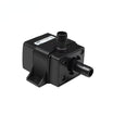
- Mini Submersible Water Pump 5V 120L/H (or the 3-5V version) - the watering pump controlled by the Arduino.
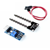
- Soil Moisture Sensor Module - moisture measurement for watering decisions (or the longer-lived capacitive version).
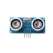
- HC-SR04 Ultrasonic Distance Sensor - monitors tank level to prevent dry-run.
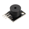
- KY-006 Piezo Buzzer - low-water alarm.
- Arduino Nano V3 - the main controller running the logic.
- Jumper wires - for interconnections.
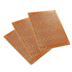
- Prototype PCBs - for the regulator board and pump switch board.
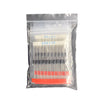
- Resistor Kit (470 Ω, 10K) and Diode Kit (1N4007 flyback) - for LED indicators and pump switching protection.
External
- 7805 regulator + capacitors, TIP120 transistor, USB connectors, LEDs - for the regulator and USB pump switch circuits.
- 9V battery, 8x AA NiMH pack, 5000 mAh power bank, weatherproof enclosure - to power and house the system.
Note: Never run a submersible pump dry. The water is its lubricant and coolant, and this design includes a tank-level lockout to protect the pump.
Step-by-Step Guide
Step 1 - Gather the Hardware
Goal: Stage everything needed for a fully independent system.
What to do: Collect the sensors, pump, Arduino, weatherproof box, and the parts needed for two small boards: a 7805-based 5V regulator for the moisture sensor and a TIP120-based USB switch for the pump. This design uses three separate battery supplies (covered in the wiring step).


Expected result: All components staged.
Step 2 - Understand the Control Logic
Goal: Understand the priority order: tank safety first, then watering.
What to do: In the main loop, the Arduino reads the ultrasonic sensor first. If the measured distance exceeds the threshold (tank low), the buzzer sounds and the pump is locked out no matter what the soil moisture sensor reports. Only when water is available does it evaluate moisture: readings at or above ~700 (dry) switch the pump ON; readings below ~500 (wet) switch it OFF. The gap between thresholds prevents rapid on/off chatter.

// Control logic summary (see the original sketch download in Credits)
if (waterLevelDistance > 20cm) {        // tank low
  soundBuzzer();
  pumpOFF();                             // lockout - never run dry
} else if (moistureValue >= 700) {       // soil dry
  pumpON();
} else if (moistureValue < 500) {        // soil wet enough
  pumpOFF();
}
Expected result: You can trace every branch of the system's behavior.
Step 3 - Build the 5V Regulator Board
Goal: Provide a clean, regulated 5V supply for the moisture sensor.
What to do: Build a classic 7805 regulator circuit: 9V battery in, regulated 5V out, with a 330 nF input and 110 nF output capacitor, plus an indicator LED through 470 Ω. This can be laid out in EasyEDA and fabricated as a PCB, or built on a prototype board.


Expected result: Steady 5V for the sensor, with an LED confirming output.
Step 4 - Build the Pump Switch Board
Goal: Let a low-current Arduino output control a higher-current pump supply.
What to do: The pump draws about 1.5 W at 5V (around 300 mA), which is far above what an Arduino I/O pin can source. Build the USB interfacing board so the Arduino drives a TIP120 transistor through a 10K resistor. The TIP120 switches the power bank's 5V (USB-B in) to the pump (USB-A out). Add a 1N4007 flyback diode for inductive kickback protection and an LED to show switch state. HIGH = watering, LOW = idle.


Expected result: Arduino-controlled pump power, safely.
Step 5 - Wire the Full System
Goal: Connect everything into one system with three power domains.
What to do: Follow the wiring diagram. The design uses three independent supplies: a NiMH pack for the Arduino, a 9V battery through the regulator for the moisture sensor, and a power bank for the pump. This is done because the Arduino's 5V rail cannot feed the ultrasonic sensor, moisture sensor, and a ~300 mA pump simultaneously. Keeping the system battery-powered also keeps mains electricity away from water and makes the unit portable.


Expected result: Every load is powered within its supply's budget.
Step 6 - Program and Deploy
Goal: Upload the sketch, mount the hardware, and deploy the system.
What to do: Compile and upload the sketch in the Arduino IDE (the original author's soilControlSystem.ino is downloadable from the credited page). Mount everything in the enclosure, drop the pump in the tank, plant the moisture probe in the soil, and aim the HC-SR04 down at the water surface.


Expected result: Dry soil triggers watering; a low tank triggers the buzzer instead of a burned-out pump.
Conclusion
You built a complete automatic irrigation system: moisture-triggered pumping with hysteresis, ultrasonic dry-run protection, a low-water alarm, proper transistor switching for the ~300 mA pump, and battery power that keeps mains away from water. This setup is portable and designed for real deployment.
Want the exact parts used in this build? Grab them from ShillehTek.com. If you want help customizing this project or building something similar for your product, check out our IoT consulting services.





.png?v=25000753014097803521789973449)

.png?v=68677308723310773341789973449)


