

Project Overview
Arduino Nano + KY-040 rotary encoder + 0.96 inch SSD1306 OLED: build a three-channel servo tester that can center, sweep, and precisely position servos, then record keyframes to EEPROM and play them back as a smooth sequence.
Before a servo goes into a robot arm, pan-tilt head, or RC plane, you typically want to confirm three things: it moves smoothly through its range, you can find true center, and multiple servos match each other. A pocket RC servo tester does this with a knob and a few modes.
This project builds an upgraded bench version using a menu on the OLED and a rotary encoder. In addition to classic tester modes, it can save poses (keyframes) and replay them, which makes it a simple teach-and-repeat controller for a 3-DOF arm.
- Time: ~1 hour
- Skill level: Beginner to Intermediate
- What you will build: A three-channel servo tester with encoder menu (center, sweep, per-servo position), keyframe recording to EEPROM, and sequence playback.

Parts List
From ShillehTek
- Arduino Nano V3 - runs the servo tester menu and playback sketch
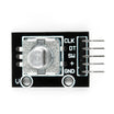
- KY-040 Rotary Encoder Module - user input for menu navigation and position control
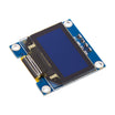
- 0.96" I2C OLED (SSD1306) - displays the menu, angles, and frame count
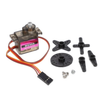
- MG90S Metal Gear Micro Servo ×3 - example servos to test and sequence (or use MG995s)
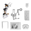
- 3-DOF Robot Arm Kit (3× MG995) - a good target project for teach-and-repeat playback
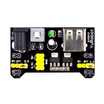
- MB102 Breadboard Power Supply - provides a separate 5 V rail for servo power
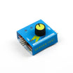
- RC Servo Tester & CCPM Checker - a no-code pocket tester for quick checks
- 830-Point Breadboard - prototyping base for the Nano and wiring
- Dupont Jumper Wires - connections between Nano, encoder, OLED, and servo signals
External
- A 5 V 2 to 3 A supply (or 9 V adapter) for the MB102 (three MG995 servos under load can draw well over 2 A)
- Arduino IDE with libraries: Adafruit SSD1306, Adafruit GFX (Servo and EEPROM are included with the IDE)
Note: Never power servos from the Nano 5V pin. Power the Nano from USB (or its own supply) and power servos from the MB102 5 V rail. Join the grounds (MB102 GND to Nano GND). Servo stalls can reset the board if you try to run them from the Nano regulator.
Step-by-Step Guide
Step 1 - Understand what a servo tester does
Goal: Know what center, sweep, and consistency checks are doing electrically.
What to do: A hobby servo expects a control pulse every 20 ms. The pulse width sets the angle (commonly about 1.0 to 2.0 ms, with about 1.5 ms as center). Pocket RC servo testers typically provide three modes: Manual (knob sets position), Neutral (fixed center pulse), and Automatic (slow sweep end-to-end).
Many pocket testers output the same signal to three headers, which is useful for checking that multiple servos move identically (often described as CCPM consistency). This Arduino Nano build reproduces those modes via a menu and adds EEPROM storage for keyframes.
Expected result: You know what you are testing for before wiring hardware.
Step 2 - Wire the encoder, OLED, servos, and power

Goal: Connect inputs, display, three servo signals, and a safe power setup with shared ground.
What to do: Wire the KY-040 rotary encoder: CLK to D2, DT to D3, SW to D4, + to 5V, GND to GND.
Wire the OLED: SDA to A4, SCL to A5, VCC to 5V, GND to GND.
Wire servo signal wires (orange/yellow) to D5, D6, D7.
Power servos separately: servo red wires to the MB102 5 V rail, servo brown/black wires to MB102 GND. Add a jumper from MB102 GND to Nano GND.
Install the Adafruit SSD1306 and Adafruit GFX libraries in the Arduino IDE. The Servo and EEPROM libraries ship with the IDE.
Expected result: Hardware is fully wired and ready for upload. Servos should not twitch yet.
Step 3 - Upload the sketch
Goal: Load the menu-driven servo tester and sequencer firmware onto the Nano.
What to do: Copy the code below into the Arduino IDE and upload to your Arduino Nano.
Code:
#include <Servo.h>
#include <Wire.h>
#include <Adafruit_GFX.h>
#include <Adafruit_SSD1306.h>
#include <EEPROM.h>

const int ENC_CLK = 2, ENC_DT = 3, ENC_SW = 4;   // KY-040
const int SERVO_PIN[3] = {5, 6, 7};
const int MAX_FRAMES = 16;                       // keyframes stored in EEPROM (byte 0 = count)
const int ITEMS = 8;
const char* NAME[ITEMS] = {"Servo 1", "Servo 2", "Servo 3", "Center all", "Sweep", "Save frame", "Play", "Clear all"};

Adafruit_SSD1306 oled(128, 64, &Wire, -1);
Servo servo[3];
int angle[3] = {90, 90, 90};
int frames = 0, menu = 0;
bool editing = false;
volatile int delta = 0;

void onEncoder() { delta += digitalRead(ENC_DT) ? 1 : -1; }   // CLK falling edge; DT gives direction

void moveAll(const int target[3], int stepDelay) {   // walk every servo 1 degree at a time to its target
  bool moving = true;
  while (moving) {
    moving = false;
    for (int i = 0; i < 3; i++) {
      if (angle[i] != target[i]) { angle[i] += (target[i] > angle[i]) ? 1 : -1; servo[i].write(angle[i]); moving = true; }
    }
    delay(stepDelay);
  }
}

void draw() {
  oled.clearDisplay();
  oled.setTextSize(1); oled.setCursor(0, 0);
  oled.print(editing ? "EDIT " : "MENU "); oled.print("frames: "); oled.print(frames);
  oled.setTextSize(2); oled.setCursor(0, 20); oled.print(NAME[menu]);
  oled.setTextSize(1); oled.setCursor(0, 50);
  oled.print(angle[0]); oled.print("  "); oled.print(angle[1]); oled.print("  "); oled.print(angle[2]);
  oled.display();
}

void setup() {
  pinMode(ENC_CLK, INPUT_PULLUP); pinMode(ENC_DT, INPUT_PULLUP); pinMode(ENC_SW, INPUT_PULLUP);
  attachInterrupt(digitalPinToInterrupt(ENC_CLK), onEncoder, FALLING);
  for (int i = 0; i < 3; i++) { servo[i].attach(SERVO_PIN[i]); servo[i].write(angle[i]); }
  oled.begin(SSD1306_SWITCHCAPVCC, 0x3C); oled.setTextColor(SSD1306_WHITE);
  frames = EEPROM.read(0); if (frames > MAX_FRAMES) frames = 0;   // fresh EEPROM reads 255
  draw();
}

void loop() {
  int d; noInterrupts(); d = delta; delta = 0; interrupts();
  if (d) {
    if (editing) { angle[menu] = constrain(angle[menu] + d, 0, 180); servo[menu].write(angle[menu]); }
    else menu = (menu + d + ITEMS * 8) % ITEMS;
    draw();
  }

  if (digitalRead(ENC_SW) == LOW) {                       // encoder click
    delay(30); while (digitalRead(ENC_SW) == LOW);        // wait for release
    if (menu < 3) {
      editing = !editing;                                 // rotate now moves this servo
    } else if (menu == 3) {                               // Center all
      int mid[3] = {90, 90, 90}; moveAll(mid, 10);
    } else if (menu == 4) {                               // Sweep: 0 -> 180 -> 90, all channels
      int lo[3] = {0, 0, 0}, hi[3] = {180, 180, 180}, mid[3] = {90, 90, 90};
      moveAll(lo, 8); delay(300); moveAll(hi, 8); delay(300); moveAll(mid, 8);
    } else if (menu == 5 && frames < MAX_FRAMES) {         // Save frame
      for (int i = 0; i < 3; i++) EEPROM.update(1 + frames * 3 + i, angle[i]);
      frames++; EEPROM.update(0, frames);
    } else if (menu == 6) {                               // Play the stored sequence
      for (int f = 0; f < frames; f++) {
        int target[3];
        for (int i = 0; i < 3; i++) target[i] = EEPROM.read(1 + f * 3 + i);
        moveAll(target, 15); delay(400);
      }
    } else if (menu == 7) {                               // Clear all
      frames = 0; EEPROM.update(0, 0);
    }
    draw();
    delay(150);
  }
}
Expected result: The OLED shows MENU, highlights Servo 1, and shows three angles at 90.
Step 4 - Verify menu and encoder behavior
Goal: Confirm the encoder scrolls the menu and click actions work.
What to do: Rotate the encoder to scroll through the eight menu items. Click the encoder on Servo 1, Servo 2, or Servo 3 to toggle EDIT mode; in EDIT, rotating the encoder changes that servo angle.
Expected result: Menu scrolling is stable and predictable, and the selected servo follows the encoder in EDIT mode.
Note: If your menu scrolls two items per click on your encoder, KY-040 modules can differ in detent behavior. Change the interrupt edge from FALLING to RISING or reduce the effective delta (for example, divide d by 2).
Step 5 - Use it as a classic servo tester
Goal: Center, sweep, and precisely position servos with angle readout.
What to do: Select Center all and click to move all three servos to 90 degrees. This is the best time to mount horns and linkages around a known neutral.
Select Sweep and click: all channels move to 0, then to 180, then back to center. Listen for grinding and watch for a lagging servo if you are comparing multiple servos.
Select Servo 1, click to enter EDIT, then rotate to move in 1 degree steps while the OLED shows the exact number. Repeat for Servo 2 and Servo 3. Use this to find real mechanical limits because some mechanisms cannot safely reach 0 or 180.
Expected result: You have a known center, verified travel, and practical min and max angles for your specific mechanics.
Step 6 - Record keyframes and play them back
Goal: Save poses to EEPROM and replay them as a smooth sequence.
What to do: Pose the mechanism by setting Servo 1, Servo 2, and Servo 3 to the first position (use EDIT on each channel as needed). Then select Save frame and click to store the pose. Repeat for additional poses up to 16 frames.
Select Play and click to replay frames in order. The moveAll() function steps each servo 1 degree at a time so all joints arrive together. Frames are stored in EEPROM so they survive power cycles. Use Clear all to wipe stored frames.
Expected result: A teach-and-repeat sequence you programmed by hand, without typing angles into code.
Step 7 - Customize the project (optional enhancements)
Goal: Extend the sketch for your own use cases without changing the core design.
What to do: You can add a Loop menu item that plays forever, store a per-frame delay so the arm can pause at a pose, or change stepDelay for different motion characteristics. You can also print angles to Serial while posing, then paste those angles into a separate robot sketch later.
Expected result: A bench tool that can evolve into a dedicated controller for your servo projects.
Conclusion
You built an Arduino Nano servo tester using a KY-040 rotary encoder and an SSD1306 OLED that can center, sweep, and precisely position three servos, then record up to 16 keyframes to EEPROM and play them back smoothly.
Want the exact parts used in this build? Grab them from ShillehTek.com. If you want help customizing this project or building something for your product, check out our IoT consulting services.
Credits: Photos and images in this tutorial are credited to John Bradnam on Hackster.io. The original guide served as a reference for this ShillehTek version.





.png?v=25000753014097803521791168436)

.png?v=68677308723310773341791168436)


