

Project Overview
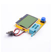
LCR-T4 transistor tester: Use the LCR-T4 transistor tester and ESR meter to identify transistors, MOSFETs, diodes, capacitors (with ESR), and inductors with one button press, then optionally build an Arduino Nano + LCD1602 version that runs the same firmware family.
Every parts drawer has a corner of mystery: transistors with the printing rubbed off, capacitors pulled from a dead power supply, or a bag of mixed diodes. The LCR-T4 answers all of it with one test. Insert the part, press TEST, and it reports what it is, which leg is which, and the numbers that matter (gain, forward voltage, capacitance, ESR, inductance).
This guide covers how to use the LCR-T4 well (including the calibration almost nobody does), what the readouts mean, how to sort your component kits with it, and how to build the Arduino Nano version so you understand what is happening inside.
- Time: About 30 minutes to master the tester; about 1 hour for the Nano build
- Skill level: Beginner
- What you will build: A calibrated component-testing workflow and (optionally) a Nano + 16x2 LCD tester that runs the same GPL firmware family as the LCR-T4

Parts List
From ShillehTek
- LCR-T4 Transistor Tester & ESR Meter - the ready-made tester used in this guide
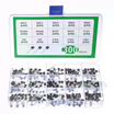
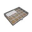
- 300-Piece Transistor Kit - S8050, S8550, S9012, S9013, S9014
- Diode Kit - 1N4148, 1N4007, 1N5819, 1N5399
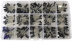
- Electrolytic Capacitor Kit - for ESR and Vloss checks
- 600-Piece Ceramic Capacitor Kit (10 pF to 10 uF) - useful for calibration and small-cap tests
- Resistor Kit - also supplies the 680 ohm and 470 kohm resistors for the Nano build
- Arduino Nano V3 - for the DIY version
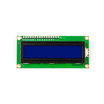
- LCD1602 16x2 Display - for the DIY version
- Tactile Button Kit - for the DIY version test button
- 830-Point Breadboard - for building the Nano version
- Dupont Jumper Wires - for breadboard wiring
External
- A 9 V battery for the LCR-T4 (or its DC input, depending on your version)
- A capacitor for calibration (about 100 nF to 20 uF; 1 uF works well)
- Optional: a contrast potentiometer for the LCD1602 (as used in common 16x2 LCD wiring)
Note: The tester measures by pushing small currents through the part, so it only works on components that are out of circuit and unpowered. Discharge every capacitor before testing. A charged electrolytic can destroy the tester input pins. Never probe a live board.
Step-by-Step Guide
Step 1 - First test
Goal: Go from box to a correct identification in about a minute.
What to do: Connect the 9 V battery. The ZIF socket has three groups of holes labeled 1, 2, and 3. Any hole in a group is the same test point, so a TO-92 transistor can go into 1, 2, 3 in whatever order the legs fit.
Lift the lever, insert the part, lower the lever, then press TEST. Take an S8050 from the transistor kit and try it.
Expected result: Something like NPN → 123=EBC → hFE=180 → Uf=690mV: the type, which test point maps to which leg (here 1 = emitter, 2 = base, 3 = collector), the DC gain, and the base-emitter forward voltage. The unit switches itself off after a while to save the battery.
Step 2 - Calibrate it (everyone skips this)
Goal: Improve accuracy on small capacitors and low resistances, and make ESR readings more trustworthy.
What to do: Short all three test points together with a bit of wire or a bent resistor lead and press TEST. When the screen offers Selftest mode?, press TEST again within a couple of seconds to accept.
The firmware runs checks, then asks you to isolate probe (remove the short). Finally it asks for a capacitor between test points 1 and 3 (about 100 nF to 20 uF; 1 uF is a good choice). It measures its own stray capacitance and internal resistance and stores the correction.
Do this once when the tester is new and again if you change the battery type.
Expected result: Small ceramic capacitor readings land closer to their marked value instead of reading high, and the ESR of a short reads near zero.
Step 3 - Read the results
Goal: Understand the key fields the tester reports.
What to do: Use these quick interpretations while testing:
- Bipolar transistors: hFE is current gain (often 100 to 300 for small-signal parts). Uf or Ube is the base-emitter drop. Any shown Ic leakage should be tiny.
- MOSFETs: Vt or Vgs(th) is the gate threshold. Cg is gate capacitance. The diode symbol is the body diode.
- Diodes: Uf is forward voltage at the test current. About 0.6 to 0.7 V is common for silicon, 0.2 to 0.4 V for Schottky, and 1.6 to 3 V for LEDs (which may light during the test).
- Capacitors: the capacitance value, plus ESR for larger values and Vloss (percentage of charge lost over a short time).
- Inductors: the inductance in mH or uH plus winding resistance.
Expected result: You can look at the screen and quickly decide whether the part is identified correctly and whether it looks healthy.
Step 4 - Sort your kits
Goal: Turn mixed or unknown parts into labeled, verified inventory.
What to do: Work through one bag or box at a time:
- Transistor kit: test one of each type and write the pinout on the bag. S8050 and S8550 are the higher-current pair (NPN and PNP). S9013 and S9012 are the general-purpose pair. S9014 is a high-gain NPN.
- Diode kit: the tester distinguishes a 1N5819 Schottky (Uf around 0.25 V) from a 1N4148 (around 0.65 V) immediately, even though they can look similar.
- Electrolytic kit: check a few parts for ESR and Vloss. A healthy 220 uF cap often reads well under 1 ohm. Several ohms of ESR or a large Vloss suggests a bad part.
- Ceramic kit: values from around 100 pF and up read cleanly. Very small values (10 to 22 pF) may be near the tester floor (around 25 pF), so expect a rough number or a question mark.
- Resistor kit: resistor pairs can be measured as a single resistance, which helps when a band color is ambiguous.
Expected result: Each kit ends up with verified values or pinouts written on it, and salvaged components get sorted into good and bad.
Step 5 - Understand how it works
Goal: Learn the simple measurement front end the firmware uses.

What to do: Each of the three test points connects to an ADC input and, through two resistors (680 ohm and 470 kohm), to two GPIO pins. The firmware sets GPIO high, low, or floating in patterns and reads all three ADCs.
A PN junction shows up as a fixed forward drop in one direction and not the other. The number and direction of junctions lets the firmware tell NPN from PNP from MOSFET from diode, and determine leg order.
Capacitance is measured by timing how long the part takes to charge through 680 ohm (larger caps) or 470 kohm (smaller caps). ESR is inferred from the voltage step when a short current pulse hits the capacitor. Inductance is derived from how fast current ramps through the 680 ohm path. Calibration matters because the firmware corrects for stray capacitance and internal resistances.
Expected result: The LCR-T4 output feels less like a black box because you know what it is measuring and why calibration helps.
Step 6 - Build the Arduino Nano version
Goal: Assemble a Nano + LCD1602 tester that behaves like the LCR-T4 and runs the related GPL firmware.
What to do: Wire the probe network like this:
- TP1: A0, with 680 ohm to D8 and 470 kohm to D9
- TP2: A1, with 680 ohm to D10 and 470 kohm to D11
- TP3: A2, with 680 ohm to D12 and 470 kohm to D13
- Test button: A3 to GND
Wire the LCD1602 in 4-bit mode as the ArduTester diagram specifies (RS to D7, E to D6, and data lines as shown in the firmware documentation, plus 5V, GND, and a contrast potentiometer). This is not the usual LiquidCrystal example pinout, so follow the diagram in the firmware package rather than habit.
Download the ArduTester 1.13 firmware (GPL, an Arduino port of the Kubbeler transistor-tester code family that the LCR-T4 also descends from). Keep all its files in one folder, open the main .ino, select Arduino Nano, and upload.
After flashing, run the same self-test process from Step 2 by shorting the three probes and following the prompts.
Expected result: Press the button with a transistor across the probes and the 16x2 LCD prints the type, pinout, and gain similar to the LCR-T4. It is not as polished as the commercial unit, but it matches the same core measurement approach.
Conclusion
The LCR-T4 transistor tester turns anonymous parts into usable ones by identifying the device type, pinout, and key parameters like hFE, Uf, ESR, and Vloss. Calibrate it once, then use it to label your component kits and quickly spot bad capacitors or mismatched diodes. If you build the Arduino Nano + LCD1602 version, the readouts make even more sense because you have wired the probe network yourself.
Want the exact parts used in this build? Grab them from ShillehTek.com. If you want help customizing this project or building something for your product, check out our IoT consulting services.
Credits
All photos and images in this tutorial are credited to Lithium ION on Hackster.io. The original guide by Lithium ION served as the reference for this ShillehTek version. We thank them for their excellent work in the maker community.






.png?v=25000753014097803521791168436)

.png?v=68677308723310773341791168436)


