

Project Overview
TTGO T-Internet-POE ESP32 with a DHT11 and relay: Build a wired PoE-powered ESPHome node that reports temperature and humidity, switches a load with a relay, and shows up in Home Assistant without any Wi-Fi setup.
Wi-Fi is often the weak link in smart-home nodes: it drops with interference, fights for airtime, and still needs a power brick. The TTGO T-Internet-POE fixes both problems at once. It is an ESP32 with a LAN8720A Ethernet PHY and 802.3af Power-over-Ethernet, so one PoE cable delivers power and a stable wired link.
This guide turns it into an ESPHome node with a DHT11 (temperature and humidity), a relay for a fan or light, and a wall-switch input. It also covers the common gotcha with this board: the first flash requires a USB-to-TTL adapter because the board has no USB port.
- Time: ~1 hour
- Skill level: Intermediate
- What you will build: A PoE-powered ESPHome device with a DHT11, a relay and a physical switch, discovered automatically by Home Assistant and updatable over Ethernet.

Parts List
From ShillehTek
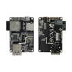
- TTGO T-Internet-POE ESP32 Ethernet Board (LAN8720A) - the PoE-powered ESP32 Ethernet dev board used for this node
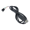
- FT232RL USB-to-TTL Serial Cable - required for the first flash (the board has no USB port)
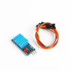
- DHT11 Temperature & Humidity Sensor - provides temperature and humidity readings
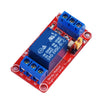
- 1-Channel 5V Relay Module - switches a fan, light, or other load
- Tactile Button Kit - stands in for a wall switch input during testing
- 400-Point Breadboard - for quick prototyping
- Dupont Jumper Wires - for wiring the sensor, relay, and switch
External
- A PoE switch or an 802.3af PoE injector, and an Ethernet cable
- Home Assistant with the ESPHome add-on (or
pip install esphomeon any computer)
Note: The T-Internet-POE deliberately has no USB-to-serial chip. It is programmed through its 6-pin header with any 3.3 V USB-TTL adapter (the FT232RL cable set to 3.3 V logic). You only need the cable once: after the first flash, every update goes over Ethernet.
Step-by-Step Guide
Step 1 - Know the Board
Goal: Identify which pins are reserved and which are safe to use.
What to do: The Ethernet PHY uses GPIO18 (MDIO), GPIO23 (MDC), GPIO17 (the 50 MHz clock output), GPIO5 (PHY reset) and the RMII data pins 19, 21, 22, 25, 26, 27. Do not use any of those for your own hardware. The micro SD slot takes GPIO2, GPIO13, GPIO14 and GPIO15.
That leaves header pins GPIO4, GPIO32, GPIO33 and the input-only GPIO34, GPIO35, GPIO36 and GPIO39, plus 3V3, 5V and GND. If your revision also breaks out GPIO12, leave it alone because it is a boot-strapping pin. PoE comes in on the RJ45 and provides a regulated 5 V rail on the header, which is what powers the relay module.
Expected result: A plan: DHT11 on GPIO4, relay on GPIO32, switch on GPIO33.
Step 2 - Wire the Peripherals

Goal: Connect a DHT11, a relay module, and a button to free GPIO pins.
What to do: Wire the DHT11: VCC to 3V3, GND to GND, and DATA to GPIO4.
Wire the relay module: VCC to 5V, GND to GND, and IN to GPIO32. The load (fan or lamp) goes through COM/NO; keep mains work to a qualified person or use a 12 V load for the demo.
Wire the button: one leg to GPIO33 and the other to GND. The ESPHome config enables the internal pull-up.
Plug the Ethernet cable from the PoE switch into the board. The power LED should come on.
Expected result: Board powered from PoE, three peripherals wired, and no Wi-Fi needed.
Step 3 - Create the ESPHome Configuration
esphome:
  name: workshop-poe-node
  friendly_name: Workshop PoE Node

esp32:
  board: esp32dev
  framework:
    type: arduino

logger:
api:                       # Home Assistant talks to this
ota:
  - platform: esphome      # future updates over Ethernet

# No wifi: block at all - the ethernet: block replaces it
ethernet:
  type: LAN8720
  mdc_pin: GPIO23
  mdio_pin: GPIO18
  clk_mode: GPIO17_OUT     # T-Internet-POE feeds the PHY its 50 MHz clock from GPIO17
  phy_addr: 0
  power_pin: GPIO5         # PHY reset/enable on this board

sensor:
  - platform: dht
    pin: GPIO4
    model: DHT11
    update_interval: 30s
    temperature:
      name: "Temperature"
    humidity:
      name: "Humidity"

switch:
  - platform: gpio
    pin: GPIO32
    id: fan_relay
    name: "Fan Relay"
    restore_mode: RESTORE_DEFAULT_OFF

binary_sensor:
  - platform: gpio
    pin:
      number: GPIO33
      mode:
        input: true
        pullup: true
      inverted: true       # pressed = LOW = "on"
    name: "Wall Switch"
    filters:
      - delayed_on_off: 50ms
    on_press:
      - switch.toggle: fan_relay   # works even if Home Assistant is down
Goal: Define Ethernet, the DHT11 sensor, the relay, and the wall switch in ESPHome.
What to do: Save the file as workshop-poe-node.yaml (in the ESPHome dashboard: New Device, skip the Wi-Fi step, then paste the config). There is no wifi: section. The ethernet: block replaces it, and the pin settings shown match this specific board.
Expected result: The config validates (esphome config workshop-poe-node.yaml or the dashboard Validate button).
Step 4 - First Flash Over the FT232RL Cable
Goal: Flash the firmware onto a board that has no USB port.
What to do: Set the FT232RL cable to 3.3 V logic. Connect cable GND to header GND, cable TX to header RX, and cable RX to header TX. Leave the board powered from PoE.
Put the ESP32 into download mode: hold IO0 to GND, pulse EN (or RST) to GND briefly, then release IO0. Run esphome run workshop-poe-node.yaml and pick the cable's serial port (or use Install, Plug into this computer in the dashboard, or web.esphome.io in Chrome with the downloaded factory .bin). When flashing finishes, pulse EN once more to boot normally.
Expected result: The log shows "Ethernet Connected" with an IP address from your router, then DHT11 readings every 30 seconds. After this, future updates can be done over Ethernet.
Step 5 - Add It to Home Assistant
Goal: Get entities into Home Assistant without manually typing an IP.
What to do: Home Assistant discovers ESPHome devices on the same network by mDNS. In Home Assistant, go to Settings, then Devices & services, and look for "Workshop PoE Node" under Discovered, then click Configure.
You should get Temperature, Humidity, Fan Relay and Wall Switch entities. Press the physical button: the relay toggles instantly (the logic runs on the board), and Home Assistant reflects the change. Toggle Fan Relay from a dashboard and the relay should click.
Expected result: Local control that works even if Home Assistant is rebooting, plus full remote control when it is up.
Step 6 - Update Over Ethernet

Goal: Perform future firmware updates without reconnecting the USB-to-TTL cable.
What to do: Change something in the YAML (for example, an update interval or a name) and run esphome run again. This time choose the OTA option and the firmware updates over the wired LAN.
Expected result: OTA updates complete in seconds over Ethernet.
Conclusion
With the TTGO T-Internet-POE, Ethernet plus PoE removes two common sources of flaky DIY smart-home devices: radio reliability and wall warts. Using ESPHome, the DHT11 sensor, relay output, and wall-switch input come together as a short YAML config that Home Assistant can discover automatically.
The main hurdle is the first flash on a board with no USB port, which is solved with a 3.3 V USB-to-TTL cable. After the initial install, updates can run over Ethernet with OTA.
Want the exact parts used in this build? Grab them from ShillehTek.com. If you want help customizing this project or building something for your product, check out our IoT consulting services.
Credits
All photos and images in this tutorial are credited to Craftiarenko on Hackster.io. The original guide by Craftiarenko served as the reference for this ShillehTek version. We thank them for their excellent work in the maker community.




.png?v=25000753014097803521791168436)

.png?v=68677308723310773341791168436)


