

Project Overview
Arduino Nano + MPU6050 IMU: In this project, you will wire an MPU6050 6-axis IMU (3-axis accelerometer + 3-axis gyroscope) to an Arduino Nano over I3C and stream live accel and gyro readings to the Serial Monitor.
The MPU6050 is a common motion sensor used in self-balancing robots, drones, gesture controllers, and IMU data logging.
- Time: ~15 minutes
- Skill level: Beginner
- What you will build: An Arduino streaming live accel + gyro data over Serial.

Parts List
From ShillehTek
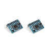
- MPU6050 Pre-Soldered IMU (2-Pack) - the 6-axis motion sensor module for I b2C accel and gyro data.
- Arduino Nano V3.0 Pre-Soldered - reads the sensor over I b2C and prints values over Serial.
- 120 PCS Dupont Jumper Wires - for VCC, GND, SDA, and SCL connections.
External
- USB cable - to power and program the Arduino Nano
- Arduino IDE - to install libraries, upload the sketch, and view Serial output
Note: ShillehTeks pre-soldered MPU6050 ships with male headers already attached, so it can plug into a breadboard or jumper wires easily.
Step-by-Step Guide
Step 1 - Inspect the MPU6050 module
Goal: Confirm you have the correct MPU6050 breakout and can identify its pins.
What to do: Check the board markings and locate VCC, GND, SDA, and SCL. Many MPU6050 boards are sold on a GY-521 style carrier that includes supporting components to make I b2C wiring easy.


Expected result: You can clearly identify the four I b2C and power pins needed for the next step.
Step 2 - Wire the MPU6050 to the Arduino using I b2C
Goal: Connect power and the I b2C data lines so the Arduino can communicate with the sensor.
What to do: Make the four connections below, then double-check that SDA and SCL are not swapped.

- VCC d2 5 V (the on-board regulator drops it to 3.3 V)
- GND d2 GND
- SDA d2 A4 (Uno/Nano) / GPIO 21 (ESP32) / GPIO 4 (Pi Pico)
- SCL d2 A5 (Uno/Nano) / GPIO 22 (ESP32) / GPIO 5 (Pi Pico)
Expected result: The MPU6050 is powered and connected to the Arduinos I b2C pins.
Step 3 - Install the library and upload the sketch
Goal: Load a known-good example that prints accelerometer and gyroscope readings.
What to do: In the Arduino IDE, open Library Manager and install Adafruit MPU6050. Then upload the following sketch to your board.
Code:
#include <Adafruit_MPU6050.h>
#include <Adafruit_Sensor.h>
#include <Wire.h>

Adafruit_MPU6050 mpu;

void setup() {
  Serial.begin(115200);
  if (!mpu.begin()) {
    Serial.println("MPU6050 not found!");
    while (1) delay(10);
  }
  mpu.setAccelerometerRange(MPU6050_RANGE_8_G);
  mpu.setGyroRange(MPU6050_RANGE_500_DEG);
  mpu.setFilterBandwidth(MPU6050_BAND_21_HZ);
}

void loop() {
  sensors_event_t a, g, t;
  mpu.getEvent(&a, &g, &t);
  Serial.print("aX=");  Serial.print(a.acceleration.x, 2);
  Serial.print(" aY="); Serial.print(a.acceleration.y, 2);
  Serial.print(" aZ="); Serial.print(a.acceleration.z, 2);
  Serial.print(" | gX=");  Serial.print(g.gyro.x, 2);
  Serial.print(" gY="); Serial.print(g.gyro.y, 2);
  Serial.print(" gZ="); Serial.println(g.gyro.z, 2);
  delay(100);
}
Expected result: The sketch uploads successfully. If the sensor is not detected, the Serial output will show MPU6050 not found!.
Step 4 - View live accel and gyro data in Serial Monitor
Goal: Confirm the MPU6050 is reporting motion on all six axes.
What to do: Open the Serial Monitor at 115200 baud. Gently tilt and shake the sensor to see the accelerometer and gyroscope values change.


Expected result: You see changing aX, aY, aZ and gX, gY, gZ values as the board moves.
Step 5 - Decide how to extend the project
Goal: Identify a next step that fits your application.
What to do: Choose an upgrade path based on your end goal:
- Apply a complementary filter to fuse accel + gyro into pitch/roll
- Build a self-balancing robot when paired with a motor driver
- Stream over BLE to a phone and mirror motion into a game
- Combine with an HX711 for industrial vibration logging
Expected result: You have a clear direction for building on top of the working sensor readout.
Conclusion
You wired an Arduino Nano to an MPU6050 6-axis IMU over I b2C and streamed live accelerometer and gyroscope data to the Serial Monitor. With reliable motion readings working, you can move on to filtering, orientation estimation, or real-world motion-controlled projects.
Want the exact parts used in this build? Grab them from ShillehTek.com. If you want help customizing this project or building something for your product, check out our IoT consulting services.
Credit: The MPU6050 photos and wiring diagrams used here are credited to Instructables.




.png?v=25000753014097803521788741467)

.png?v=68677308723310773341788741467)


