


Project Overview
Arduino Nano + KY-018 photoresistors + L298N: In this build you make a light-following robot where two LDR sensors act like eyes, and differential steering drives two DC motors toward the brightest light source.
Two photoresistors (LDRs) detect which side is brighter, the Arduino compares the readings, and two motors steer the chassis toward the light. Shine a flashlight and watch the robot chase it.
This guide wires the KY-018 photoresistor module (or bare LDRs with 10 k pull-down resistors), connects two DC motors through an L298N motor driver, and programs the differential steering behavior.
- Time: About 60 minutes
- Skill level: Beginner
- What you will build: A two-sensor Arduino robot that turns and drives toward a bright light.
Parts List
From ShillehTek
- Arduino Nano V3.0 - reads the two photoresistor signals and controls motor speed and direction.
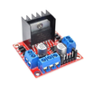
- L298N Motor Driver - drives two DC motors from a battery pack using Arduino control pins.
- Breadboard + jumper wires - quick prototyping for the sensors and signal wiring.
- 820pc Resistor Kit - includes 10 k resistors if you are using bare LDRs (not KY-018 modules).
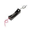
- 18650 Battery Holder - motor power option (a 4x AA holder also works).
External
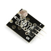
- Two KY-018 photoresistor modules (or two bare LDRs + two 10 k resistors).
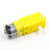
- Two DC gearmotors + wheels (yellow TT motors are common).
- Chassis (2-wheel + caster).
- 4x AA battery holder or single 18650 pack (for motor power).
- Flashlight or bright phone light for testing.
Note: If you use the L298N for motor power from a battery pack, make sure the Arduino GND is connected to the L298N/battery negative (shared ground), and ensure your motor supply voltage matches your motors.
Step-by-Step Guide
Step 1 - Understand how photoresistors work
Goal: Know what the LDR output means so you can wire and tune it correctly.
What to do: A photoresistor (LDR) is a semiconductor whose resistance drops in bright light. Typical values can range from about 10 M in darkness to about 10 k in room light and around 500 in direct sunlight.
Wire a bare LDR as the top half of a voltage divider (LDR to +5V, 10 k pull-down to GND, analog input pin in the middle). The ADC then reads a voltage proportional to light. On the KY-018 module the divider is already built in, so you get three pins: VCC, GND, AOUT.

Expected result: You can explain why brighter light changes the analog reading and why two sensors let the robot decide which way to turn.
Step 2 - Wire the two-eye sensor setup and motor driver
Goal: Connect two KY-018 sensors to A0/A1 and connect the L298N to the Arduino pins for differential steering.
What to do: Wire the two sensors to 5V, GND, and separate analog inputs, then wire the L298N input pins and enable (PWM) pins to the Arduino. Connect your motor battery pack to the L298N motor power input, and connect battery negative to Arduino GND so they share ground.
Wiring map:
Left KY-018      Arduino Nano
VCC          -> 5V
GND          -> GND
AOUT         -> A0

Right KY-018     Arduino Nano
VCC          -> 5V
GND          -> GND
AOUT         -> A1

L298N            Arduino Nano
IN1          -> D5  (left motor direction A)
IN2          -> D6  (left motor direction B)
IN3          -> D9  (right motor direction A)
IN4          -> D10 (right motor direction B)
ENA          -> D3  (left PWM speed)
ENB          -> D11 (right PWM speed)
+12V         -> battery pack +
GND          -> battery pack - + Arduino GND
Mount the two LDRs facing forward and angled slightly outward, about 5 cm apart at the front of the robot.
Expected result: Both sensors read on A0 and A1, and the L298N is ready to drive each motor forward or backward with PWM speed control.
Step 3 - Upload the differential-steering Arduino sketch
Goal: Make the robot turn toward the brighter sensor by speeding up one motor and slowing the other.
What to do: Upload the sketch below. It reads both analog inputs, computes the difference, and adjusts the left and right motor PWM values around a base speed.
Code:
const int LEFT_LDR  = A0;
const int RIGHT_LDR = A1;
const int LEFT_PWM  = 3;
const int RIGHT_PWM = 11;
const int L_A = 5, L_B = 6;
const int R_A = 9, R_B = 10;
const int BASE_SPEED = 150;

void setMotor(int a, int b, int pwm, int speed) {
  digitalWrite(a, speed > 0 ? HIGH : LOW);
  digitalWrite(b, speed > 0 ? LOW : HIGH);
  analogWrite(pwm, abs(speed));
}

void setup() {
  pinMode(L_A, OUTPUT); pinMode(L_B, OUTPUT);
  pinMode(R_A, OUTPUT); pinMode(R_B, OUTPUT);
}

void loop() {
  int L = analogRead(LEFT_LDR);
  int R = analogRead(RIGHT_LDR);
  int diff = L - R;     // positive = light is on left side

  int leftSpeed  = BASE_SPEED - diff / 4;
  int rightSpeed = BASE_SPEED + diff / 4;
  leftSpeed  = constrain(leftSpeed, 0, 255);
  rightSpeed = constrain(rightSpeed, 0, 255);

  setMotor(L_A, L_B, LEFT_PWM,  leftSpeed);
  setMotor(R_A, R_B, RIGHT_PWM, rightSpeed);

  delay(50);
}
Expected result: If the left LDR sees brighter light, the left motor slows and the right motor speeds up so the robot turns left. If the right LDR sees brighter light, it turns right. Balanced light drives it forward.
Step 4 - Calibrate the behavior for your room lighting
Goal: Prevent wandering when the room is too dark and make the response stable under your ambient light.
What to do: Ambient light varies. Print the raw LDR values with the flashlight ON and OFF and pick a threshold. You can also add a simple stop condition so the robot stops when it is too dark to see anything.
Code (optional stop check):
if (L < 100 && R < 100) {
  // too dark, stop
  analogWrite(LEFT_PWM, 0);
  analogWrite(RIGHT_PWM, 0);
  return;
}
Expected result: In low light the robot stops instead of driving randomly, and with a flashlight it reliably turns toward the brighter side.
Step 5 - Try the line-following variant (same hardware)
Goal: Reuse the same sensors and steering logic to follow a dark line on a bright surface.
What to do: Keep the wiring the same, but mount the LDRs facing downward a few cm above the ground. A dark line reflects less light than a white surface, so the differential steering traces the line.

Expected result: The robot steers to keep the sensor readings balanced while moving along the line.
Step 6 - Explore where this sensor pattern leads
Goal: Understand how the same two-sensor comparison approach applies to other builds.
What to do: Use the same idea of comparing two sensor inputs and steering toward the difference.
- Automatic solar tracker: same two-LDR pattern but drives a servo instead of wheels.
- Sunflower art installation: multiple servos + LDRs to face the brightest light source.
- Interactive room lighting: LDRs decide when to trigger relays based on ambient light.
- Turtle-style crawler: three LDRs for triangulated homing on a specific light.
Expected result: You can reuse the exact same “two sensors + difference” logic for new motion and control projects.
Conclusion
With an Arduino Nano, two photoresistors (KY-018 or bare LDRs), and an L298N motor driver, you can build a real autonomous light-following robot using differential steering. The same pattern also works for line-following and other sensor-guided motion projects.
Inspiration credit: Arduino Flashlight Following Robot on Instructables.
Want the exact parts used in this build? Grab them from ShillehTek.com. If you want help customizing this project or building something for your product, check out our IoT consulting services.






.png?v=25000753014097803521791168436)

.png?v=68677308723310773341791168436)


