

MAX30102 Optical Pulse Sensor Learning Kit with ESP32 & OLED
SKU ST-KIT-09
In stock now
MAX30102 optical pulse learning kit with ESP32, a blue SSD1306 OLED, breadboard and jumpers. Develop your own wiring and firmware for educational sensor experiments; not for diagnosis or health monitoring.
- Free Ground Shipping U.S. orders $35+
- Ships from USA Worldwide via DHL
- 30-day returns Free defect replacement
- 7-day support Fast email replies
 MAX30102 Optical Pulse Sensor Learning Kit with ESP32 & OLEDNo reviews yet
$26.99
This item


Products related to this item
Overview
Product Overview
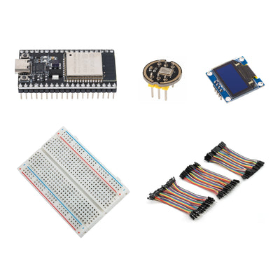
Explore optical pulse-waveform data with the MAX30102 Optical Pulse Sensor Learning Kit. A pre-soldered 38-pin ESP32 USB-C board with 4MB flash provides the controller, and the MAX30102 sensor connects to your experimental firmware over I2C. Use the 0.96-inch blue SSD1306 OLED to display your own sample data or project status while learning sensor communication and signal processing. The kit includes a 400-point breadboard and 10cm jumpers for wiring separate components. Assembly and firmware development are required. This is an educational experiment kit, not a device for medical diagnosis or health monitoring.
Bundle value: Purchased separately, the included component variants total $32.61. This kit is $26.99, saving $5.62.
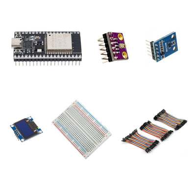
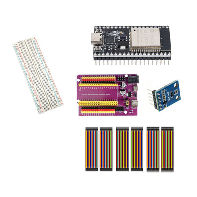
- 1 × pre-soldered 38-pin ESP32 USB-C board with 4MB flash
- 1 × pre-soldered MAX30102 optical pulse sensor module
- 1 × 0.96-inch blue SSD1306 I2C OLED display
- 1 × 400-point solderless breadboard
- 1 × 120-piece, 10cm jumper wire set: male–male, male–female and female–female
This kit is for educational experiments, not medical diagnosis or health monitoring. Wiring and your own firmware are required. A USB-C data cable, computer, power source and enclosure are not included. Measurements depend on your software and setup; no medical accuracy or diagnostic performance is claimed.
Read the kit setup guide for assembly planning, required extras and component references.
Questions & answers
Frequently asked questions
Have other questions?
Chat with our US-based team — we usually reply fast.
What's included
Features & Specs
Reference
Documents
Full Product Manual MAX30102 Optical Pulse Sensor Learning Kit with ESP32 & OLED — Setup Guide In-depth setup guide with wiring, code examples, and troubleshooting.Learn
Related Tutorials

Verified buyers
Customer Reviews
MAX30102 Optical Pulse Sensor Learning Kit with ESP32 & OLED
