Overview
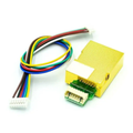
The R307S is an optical fingerprint sensor module that handles the entire biometric workflow — capturing the fingerprint image, converting it to a template, storing it, and matching it — on the module itself. Your microcontroller simply sends short commands over a serial connection and receives clean answers like "finger #7 matched with confidence 154". That makes it a practical way to add fingerprint access control to Arduino, ESP32, Raspberry Pi, and Raspberry Pi Pico projects without any image processing on your side.
Under the glass window, an LED-illuminated optical sensor captures a 256 x 288 pixel image at 500 DPI. The onboard DSP converts each enrolled finger into a compact 512-byte template and can store up to 1000 of them in its internal flash, searching the whole library in under a second. The module talks over a TTL UART (57600 baud by default) through the included 6-pin cable, and the board also exposes USB data pads if you want to connect it directly to a PC for enrollment with the vendor tools. The R307S revision adds a touch-sense circuit: power pin 6 with 3.3V and pin 5 goes high the moment a finger rests on the window, which is perfect for waking a sleeping microcontroller.
Well-supported libraries exist for every platform — Adafruit's Fingerprint Sensor library for Arduino and ESP32, and pyfingerprint for Raspberry Pi — so enrollment and matching are a few function calls away. As with any hobby-grade biometric module, treat it as a convenience layer for maker projects, not as certified high-security hardware for protecting anything critical.
At a Glance
Specifications
| Parameter | Value |
| Sensor Type | Optical fingerprint sensor (LED illuminated) |
| Supply Voltage | DC 4.2V - 6.0V (5V typical) |
| Working Current | ~50 mA typical (peak <80 mA) |
| Interface | UART TTL (3.3V logic) + USB 2.0 pads |
| Default Baud Rate | 57600 (configurable 9600 - 115200) |
| Image Resolution | 256 x 288 pixels, 500 DPI |
| Template Capacity | 1000 fingerprints (512-byte templates) |
| False Accept Rate (FAR) | <0.001% |
| False Reject Rate (FRR) | <1.0% |
| Search Time | <1.0 s (1:N against full library) |
| Matching Modes | 1:1 verification and 1:N identification |
| Touch Sense | Finger-detect output (pin 5), powered by 3.3V on pin 6 |
Pinout Diagram
The 6-pin cable connector carries everything you need: pin 1 is +5V power, pin 2 is ground, and pins 3 (TXD) and 4 (RXD) are the TTL serial lines — remember that TXD on the sensor connects to your board's RX, and RXD connects to your board's TX. Pins 5 and 6 are the optional touch-sense feature: feed 3.3V into pin 6 and pin 5 outputs a signal whenever a finger touches the window, even before any serial command is sent. The two pads marked 3.3V near the connector can be shorted to configure the interface for 3.3V systems, and the four USB pads (5V, D+, D-, GND) let you wire the module straight to a PC as a USB fingerprint reader.

Wiring Guide
Arduino Wiring
On an Uno or Nano the hardware serial port is used by USB, so the sensor goes on a SoftwareSerial port using pins 2 and 3. Power comes from the 5V pin.
| R307S Pin | Arduino Pin | Details |
|---|---|---|
| 1 (+5V) | 5V | |
| 2 (GND) | GND | |
| 3 (TXD) | D2 | SoftwareSerial RX |
| 4 (RXD) | D3 | SoftwareSerial TX - via voltage divider |
| 5 (Touch Sense) | D4 | Optional finger-detect input |
| 6 (Touch Sense Power) | 3.3V | Optional, powers the touch circuit |
ESP32 Wiring
The ESP32's second hardware UART (Serial2 on GPIO 16/17) is ideal for the R307S. Power the module from VIN (5V) while the 3.3V ESP32 logic matches the sensor's serial levels directly — no divider needed.
| R307S Pin | ESP32 Pin | Details |
|---|---|---|
| 1 (+5V) | VIN (5V) | Sensor needs 4.2-6V supply |
| 2 (GND) | GND | |
| 3 (TXD) | GPIO 16 (RX2) | 3.3V logic - direct |
| 4 (RXD) | GPIO 17 (TX2) | 3.3V logic - direct |
| 5 (Touch Sense) | GPIO 4 | Optional, can be a wake-up source |
| 6 (Touch Sense Power) | 3V3 | Optional, powers the touch circuit |
Raspberry Pi Wiring
The sensor connects to the Pi's GPIO UART. First free up the serial port: run sudo raspi-config, go to Interface Options > Serial Port, answer "No" to the login shell and "Yes" to enabling the serial hardware, then reboot.
| R307S Pin | Raspberry Pi Pin | Details |
|---|---|---|
| 1 (+5V) | Pin 2 (5V) | |
| 2 (GND) | Pin 6 (GND) | |
| 3 (TXD) | Pin 10 (GPIO 15, RXD) | 3.3V logic - direct |
| 4 (RXD) | Pin 8 (GPIO 14, TXD) | 3.3V logic - direct |
| 5 (Touch Sense) | Pin 7 (GPIO 4) | Optional finger-detect input |
| 6 (Touch Sense Power) | Pin 1 (3.3V) | Optional, powers the touch circuit |
Raspberry Pi Pico Wiring
The Pico's UART0 on GP0/GP1 handles the sensor, with 5V power taken from VBUS while USB is connected.
| R307S Pin | Pico Pin | Details |
|---|---|---|
| 1 (+5V) | VBUS (pin 40) | 5V from USB |
| 2 (GND) | GND (pin 38) | |
| 3 (TXD) | GP1 (pin 2, UART0 RX) | 3.3V logic - direct |
| 4 (RXD) | GP0 (pin 1, UART0 TX) | 3.3V logic - direct |
| 5 (Touch Sense) | GP2 (pin 4) | Optional finger-detect input |
| 6 (Touch Sense Power) | 3V3(OUT) (pin 36) | Optional, powers the touch circuit |
Code Examples
Arduino
Install the "Adafruit Fingerprint Sensor Library" from the Library Manager. Run its bundled enroll example once to store fingers, then use this sketch to recognize them.
// R307S Fingerprint Sensor - Arduino Example
// Sensor TXD -> D2, Sensor RXD -> D3 (via divider), +5V -> 5V, GND -> GND
// Library: "Adafruit Fingerprint Sensor Library" (Library Manager)

#include <Adafruit_Fingerprint.h>
#include <SoftwareSerial.h>

SoftwareSerial mySerial(2, 3);  // RX = D2 (from TXD), TX = D3 (to RXD)
Adafruit_Fingerprint finger = Adafruit_Fingerprint(&mySerial);

void setup() {
  Serial.begin(9600);
  finger.begin(57600);  // R307S default baud rate

  if (finger.verifyPassword()) {
    Serial.println("Fingerprint sensor found!");
  } else {
    Serial.println("Sensor not found - check wiring and baud rate.");
    while (1) delay(1);
  }

  finger.getTemplateCount();
  Serial.print("Templates stored: ");
  Serial.println(finger.templateCount);
  Serial.println("Place an enrolled finger on the window...");
}

void loop() {
  // Step 1: capture an image of the finger
  if (finger.getImage() != FINGERPRINT_OK) return;

  // Step 2: convert the image to a search template
  if (finger.image2Tz() != FINGERPRINT_OK) return;

  // Step 3: search the stored library for a match
  if (finger.fingerFastSearch() == FINGERPRINT_OK) {
    Serial.print("Match! ID #");
    Serial.print(finger.fingerID);
    Serial.print(" (confidence ");
    Serial.print(finger.confidence);
    Serial.println(")");
    delay(1000);  // Debounce so one touch prints once
  } else {
    Serial.println("No match for this finger.");
    delay(500);
  }
}
ESP32 (Arduino IDE)
// R307S Fingerprint Sensor - ESP32 Example
// Sensor TXD -> GPIO 16 (RX2), Sensor RXD -> GPIO 17 (TX2), +5V -> VIN
// Library: "Adafruit Fingerprint Sensor Library" (Library Manager)

#include <Adafruit_Fingerprint.h>

// Use the ESP32's second hardware UART - no SoftwareSerial needed
HardwareSerial sensorSerial(2);  // UART2
Adafruit_Fingerprint finger = Adafruit_Fingerprint(&sensorSerial);

void setup() {
  Serial.begin(115200);

  // begin(baud, config, RX pin, TX pin)
  sensorSerial.begin(57600, SERIAL_8N1, 16, 17);
  finger.begin(57600);

  if (finger.verifyPassword()) {
    Serial.println("Fingerprint sensor found!");
  } else {
    Serial.println("Sensor not found - check wiring.");
    while (1) delay(1);
  }

  Serial.println("Place an enrolled finger on the window...");
}

void loop() {
  if (finger.getImage() != FINGERPRINT_OK) return;
  if (finger.image2Tz() != FINGERPRINT_OK) return;

  if (finger.fingerFastSearch() == FINGERPRINT_OK) {
    Serial.printf("Match! ID #%d (confidence %d)\n",
                  finger.fingerID, finger.confidence);
    delay(1000);
  } else {
    Serial.println("No match for this finger.");
    delay(500);
  }
}
Raspberry Pi (Python)
Install the driver with pip3 install pyfingerprint (in a virtual environment on newer Raspberry Pi OS). Enable the serial port in raspi-config first as described in the wiring tab.
#!/usr/bin/env python3
# R307S Fingerprint Sensor - Raspberry Pi Example
# Sensor TXD -> GPIO 15 (pin 10), Sensor RXD -> GPIO 14 (pin 8)
# Setup: sudo raspi-config (disable serial console, enable serial port)
#        pip3 install pyfingerprint

import time
from pyfingerprint.pyfingerprint import PyFingerprint

# Open the Pi's GPIO UART at the sensor's default settings
f = PyFingerprint('/dev/serial0', 57600, 0xFFFFFFFF, 0x00000000)

if not f.verifyPassword():
    raise ValueError('Sensor password check failed - check wiring/baud')

print('Sensor found. Templates used: {}/{}'.format(
    f.getTemplateCount(), f.getStorageCapacity()))
print('Place an enrolled finger on the window (Ctrl+C to stop)...')

try:
    while True:
        # Wait for a finger and capture the image
        if f.readImage():
            # Convert to characteristics in char buffer 1
            f.convertImage(0x01)

            # Search the template library
            position, accuracy = f.searchTemplate()

            if position >= 0:
                print('Match! Template #{} (accuracy {})'.format(
                    position, accuracy))
                time.sleep(1)
            else:
                print('No match for this finger.')
                time.sleep(0.5)
        time.sleep(0.05)

except KeyboardInterrupt:
    print('Stopped by user')
Raspberry Pi Pico (MicroPython)
This dependency-free example speaks the sensor's packet protocol directly over UART0: it verifies communication, then polls for a finger and reports when one is captured — a solid starting point for building enrollment and matching on the Pico.
# R307S Fingerprint Sensor - Pico MicroPython Example
# Sensor TXD -> GP1 (UART0 RX), Sensor RXD -> GP0 (UART0 TX), +5V -> VBUS
# Talks the raw protocol - no library needed.

from machine import UART, Pin
import time

uart = UART(0, baudrate=57600, tx=Pin(0), rx=Pin(1), timeout=500)

HEADER = b'\xef\x01'
ADDRESS = b'\xff\xff\xff\xff'

def send_cmd(payload):
    # payload = instruction + parameters (without length/checksum)
    length = len(payload) + 2
    packet = b'\x01' + bytes([length >> 8, length & 0xFF]) + payload
    checksum = sum(packet)
    frame = HEADER + ADDRESS + packet + bytes(
        [(checksum >> 8) & 0xFF, checksum & 0xFF])
    uart.write(frame)

def read_ack():
    time.sleep_ms(100)
    resp = uart.read()
    if resp and len(resp) >= 12 and resp[:2] == HEADER:
        return resp[9]  # confirmation code: 0x00 = success
    return None

# --- Check the sensor answers (VfyPwd with default password 0x00000000)
send_cmd(b'\x13\x00\x00\x00\x00')
if read_ack() == 0x00:
    print('Fingerprint sensor found!')
else:
    raise RuntimeError('Sensor not responding - check wiring and baud')

print('Touch the sensor window...')

while True:
    # GenImg: capture a fingerprint image if a finger is present
    send_cmd(b'\x01')
    code = read_ack()

    if code == 0x00:
        print('Finger detected and image captured!')
        time.sleep(1)   # Debounce so one touch prints once
    # 0x02 means "no finger on the window" - keep polling quietly
    time.sleep_ms(200)