ESP32-CAM 4WD Smart Robot Car Kit with WiFi App Control (Battery Not Included)Default Title · $49.99 · Only 3 left
Overview
This kit turns an ESP32-CAM into something genuinely fun: a four-wheel-drive robot car you steer from a phone or browser while watching a live video feed from the car itself. The ESP32-CAM supplies the brains, the Wi-Fi, and the OV2640 camera in one small board; the chassis supplies four TT gear motors, wheels, and the mounting deck; a motor driver stage sits between them so the ESP32’s logic pins can command motor-sized currents.
It is equal parts robotics project and ESP32 course. Building it walks you through the full embedded stack — assembling a drivetrain, flashing firmware from the Arduino IDE (including the ESP32-CAM’s famous GPIO 0 boot-mode ritual), serving a control page over Wi-Fi, and streaming camera frames — and when it is done you have an untethered, camera-equipped rover to extend however you like.
Two expectations before the first screw: batteries are not included (the drivetrain wants 18650 cells), and power discipline is the whole game with this board — most “my ESP32-CAM keeps resetting” stories are power stories. This manual covers assembly order, flashing, motor wiring, the power and app-control setup, working code, and the fixes for the classic ESP32-CAM gotchas.
Wi-Fi — ESP32 hosts its own access point (or joins your network)
Interface
Phone app / any browser: video + drive controls
Power
18650 Li-ion cells (not included); holder on chassis
Flashing
USB-serial adapter, GPIO 0 to GND for boot mode
Firmware
Arduino IDE with the ESP32 board package
Chassis
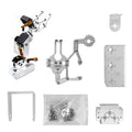
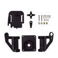
Layered deck with pre-cut mounts, assembly required
Wiring Guide
Build Order That Avoids Rework
Step
What to do
Notes
1. Motors to chassis
Bolt the 4 TT motors to the lower deck
Solder/attach motor leads BEFORE mounting — far easier
2. Wheels
Press wheels onto the motor shafts
Shafts are keyed — align the flats
3. Electronics deck
Mount driver board, battery holder, ESP32-CAM
Camera facing forward, antenna clear of metal
4. Wiring
Motors → driver, driver → ESP32, power last
See the Motor Wiring and Power tabs
5. Bench test
Wheels-up test before the maiden drive
Confirm each wheel’s direction, fix reversed pairs
Label left and right. In a 4WD skid-steer car, the two left motors act as one channel and the two right motors as the other. Mark the leads as you go — a single swapped pair makes the car spin instead of drive, and finding it after full assembly is the annoying way.
Flashing: USB-Serial Adapter to ESP32-CAM
Adapter Pin
ESP32-CAM Pin
Notes
5V
5V
Power for flashing (or 3.3V → 3.3V, pick one)
GND
GND
Common ground
TX
U0R (GPIO 3)
Adapter transmit → board receive
RX
U0T (GPIO 1)
Board transmit → adapter receive
Boot mode
GPIO 0 → GND
Jumper ON while uploading, OFF to run
The ritual. Jumper GPIO 0 to GND, press the board’s reset button, upload from the Arduino IDE (board: “AI Thinker ESP32-CAM”), then remove the jumper and reset again to run. Kits that include a programming shield/board do the same thing with a built-in USB port — use it if yours has one.
Motors to Driver to ESP32
Connection
From → To
Notes
Left motor pair
Both left motors → driver output A
Wired in parallel, matching polarity
Right motor pair
Both right motors → driver output B
Wired in parallel, matching polarity
Direction inputs
Driver IN pins → ESP32-CAM GPIO 12 / 13 / 14 / 15
The free GPIOs on an ESP32-CAM; match your firmware’s pin map
Driver logic power
Driver 5 V logic → shared 5 V rail
Per your driver board’s markings
Grounds
Driver GND ↔ ESP32 GND ↔ battery −
One common ground, always
Pin real estate is tight. The camera claims most of the ESP32-CAM’s pins; GPIO 12, 13, 14, 15 (and 2/4, shared with the SD card and flash LED) are what remains. Whatever sketch you flash, make sure its motor pin definitions match your physical wiring — that mapping is the #1 source of “video works, wheels don’t.”
Power and Driving It
Item
Setup
Notes
Batteries
18650 cells in the holder (not included)
Use quality protected cells; observe polarity
Battery feed
Holder → driver board motor supply
Driver’s 5 V output (or converter) feeds the ESP32-CAM
Switch off to charge
Remove cells for external charging
The kit does not charge cells in place
Connect
Join the car’s Wi-Fi access point from your phone
Then open the control page in the app/browser
Drive
On-screen controls + live camera stream
Streams best within typical home Wi-Fi range
Never drive motors from the flashing adapter. A USB-serial adapter can power the bare board for flashing, but motors stall-spike far beyond what it supplies — that path leads to brownout resets and confused debugging. Batteries for driving, adapter for flashing, and the camera + Wi-Fi alone want a solid 5 V at several hundred mA.
Code Examples
1. First Flash — Camera Web Server
camera-first-flash.txt
Arduino IDE setup for the ESP32-CAM:
1. File > Preferences > Additional Boards Manager URLs:
   https://espressif.github.io/arduino-esp32/package_esp32_index.json
2. Tools > Board > Boards Manager > install "esp32"
3. Tools > Board > "AI Thinker ESP32-CAM"
4. File > Examples > ESP32 > Camera > CameraWebServer
   - select CAMERA_MODEL_AI_THINKER in the sketch
   - enter your Wi-Fi SSID and password
5. GPIO 0 jumper ON, reset, Upload; jumper OFF, reset
6. Open Serial Monitor (115200) - it prints the stream URL
7. Visit that URL in a browser: live video confirms the
   board, camera, and Wi-Fi all work before the car does
2. Motor Test — Wheels-Up Sanity Check
motor_test.ino
// Bench test with the car's wheels OFF the ground.
// Match these pins to your driver wiring (Motor Wiring tab).
const int L_FWD = 12, L_REV = 13;   // left pair
const int R_FWD = 14, R_REV = 15;   // right pair

void setup() {
  pinMode(L_FWD, OUTPUT); pinMode(L_REV, OUTPUT);
  pinMode(R_FWD, OUTPUT); pinMode(R_REV, OUTPUT);
}

void allStop() {
  digitalWrite(L_FWD, LOW); digitalWrite(L_REV, LOW);
  digitalWrite(R_FWD, LOW); digitalWrite(R_REV, LOW);
}

void loop() {
  // forward - all four wheels should spin the same way
  digitalWrite(L_FWD, HIGH); digitalWrite(R_FWD, HIGH);
  delay(1500);
  allStop(); delay(500);

  // spin in place - left pair back, right pair forward
  digitalWrite(L_REV, HIGH); digitalWrite(R_FWD, HIGH);
  delay(1500);
  allStop(); delay(1500);
  // Any wheel turning the wrong way: swap that motor's two leads.
}
"Brownout detector was triggered" in the Serial Monitor means
the 5V rail sagged. Work down this list:

1. Fresh / charged 18650 cells (tired cells sag under motor load)
2. Motors on battery power, never on the USB-serial adapter
3. Thick, short power leads to the ESP32-CAM; add a 470-1000 uF
   capacitor across its 5V/GND if resets happen when motors start
4. Camera + Wi-Fi alone can draw ~300 mA peaks - budget for it
5. Antenna near battery leads or metal deck = weak Wi-Fi;
   reposition the board so the antenna area hangs clear
Frequently Asked Questions
Which batteries do I need, exactly?
18650 lithium-ion cells to suit the kit’s holder — buy quality name-brand protected cells from a reputable seller, and a proper 18650 charger. Avoid the no-name cells with implausible mAh claims; sagging fake cells are the root cause of half of all robot-car misbehavior.
The board keeps resetting, especially when the motors kick in. Why?
That is the ESP32-CAM brownout, the platform’s signature ailment. The camera and Wi-Fi already draw hard; a motor start-up sags the rail past the brownout threshold and the chip reboots. Charged cells, motors on battery (never the flashing adapter), short thick power wires, and a fat capacitor across the ESP32’s supply fix it in that order.
Upload fails or the sketch won’t flash. What am I missing?
The boot-mode ritual: GPIO 0 jumpered to GND, then reset, then upload — and remove the jumper and reset again afterward to run. Also check TX/RX are crossed (adapter TX to U0R), the board selection is “AI Thinker ESP32-CAM”, and nothing else is holding the serial lines. Boards with a programming shield skip the jumper dance entirely.
“Camera init failed” — is my camera dead?
Rarely. It usually means the wrong camera model was selected in the sketch (use CAMERA_MODEL_AI_THINKER), PSRAM is disabled in the IDE settings, or the camera’s ribbon cable popped loose — open the connector latch, reseat the ribbon squarely, and close it. Actual dead OV2640s are the rare last resort of that list.
How far can I drive it, and why does video lag?
Range is ordinary Wi-Fi range — solid within a home or classroom, shrinking with walls and interference. Latency comes from the MJPEG stream: lower the resolution or JPEG quality in the camera settings for a snappier feed. In AP mode, staying reasonably close to the car keeps both control and video responsive.
Can I add sensors like ultrasonic obstacle avoidance?
Yes, but budget pins first: with the camera in use, only a handful of GPIOs (12–15, plus 2/4 with caveats) exist, and this build spends four on motors. Options: drive the motors through fewer pins (a driver with a latch or I2C), hang sensors off spare pins like GPIO 2, or add a second small MCU for sensing that talks to the ESP32-CAM over serial.
Do I need the app, or does a browser work?
A browser is enough — the car serves its control page and video over HTTP, so anything with a browser on the same Wi-Fi can drive it (that is exactly what the minimal drive server example does). Apps add nicer joysticks and layouts, but they are a convenience on top of the same underlying web endpoints.
Reference documents for the ESP32-CAM 4WD Smart Robot Car Kit with WiFi App Control (Battery Not Included). This manual covers wiring and code; the documents below carry the full electrical specifications.