Overview
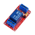
The ShillehTek 1-Channel 12V Relay Module lets an Arduino, Raspberry Pi, ESP32, or Raspberry Pi Pico switch a single high-voltage or high-current load with a low-voltage logic signal — while running the relay coil itself from a 12V supply. The 12V coil is well suited to projects that already include a 12V rail (automotive electronics, LED strips, door locks, water pumps, automation panels) and provides stronger contact pressure than the 5V variant.
The on-board SRD-12VDC-SL-C relay can switch up to 10A at 250VAC or 10A at 30VDC. It is opto-coupled and uses an active-LOW input — pull the IN pin LOW to energize the coil. A red LED indicates relay state and a green LED indicates power. Three screw terminals (NO, COM, NC) provide both Normally Open and Normally Closed switching options.
Because the coil needs 12V, this module requires an external 12V supply for VCC — your microcontroller's 5V rail cannot power it. The IN pin is still driven by 3.3V or 5V logic, just like the 5V version.
At a Glance
Specifications
| Parameter | Value |
| Coil / Module Voltage | 12V DC |
| Trigger Current | ~30-40 mA per channel (at 12V) |
| Trigger Logic | Active LOW (LOW = relay ON) |
| Trigger Voltage Range | 0V (ON) / 3.3V-5V (OFF) |
| Max Switching Voltage | 250V AC / 30V DC |
| Max Switching Current | 10 A |
| Relay Part | SONGLE SRD-12VDC-SL-C |
| Output Configuration | SPDT (NO / COM / NC) |
| Indicator LEDs | Power (green), Relay state (red) |
| Mounting | 2 screw holes |
| Dimensions (approx.) | 50 x 26 x 18 mm |
Pinout Diagram

Wiring Guide
Arduino Wiring
The 12V relay module needs an external 12V power supply for the coil — do not power VCC from the Arduino. Connect the supply's 12V to VCC, the supply's GND to the module's GND and to Arduino GND (shared ground is required), and drive IN from any digital pin.
| Module Pin | Connect To | Details |
|---|---|---|
| VCC | External 12V supply (+) | NOT Arduino 5V |
| GND | Supply (-) + Arduino GND | Shared ground required |
| IN | Arduino Digital Pin 7 | Active LOW |
Load wiring (typical, switch high-side of a load):
| Screw Terminal | Connect To |
|---|---|
| COM | One leg of the load circuit |
| NO | Other leg returning to source |
| NC | Leave unused (or wire your "default ON" load) |
digitalWrite(relayPin, LOW) energizes the relay; HIGH releases it. Initialize the pin HIGH in setup() so the relay does not click ON during boot.
ESP32 Wiring
The ESP32 uses 3.3V GPIO, which is enough to drive the IN pin's opto-isolator. The 12V coil supply must come from an external source. Tie all grounds together — ESP32 GND, 12V supply GND, and module GND.
| Module Pin | Connect To | Details |
|---|---|---|
| VCC | External 12V supply (+) | NOT ESP32 VIN |
| GND | Supply (-) + ESP32 GND | Shared ground required |
| IN | GPIO 23 | 3.3V drives opto reliably |
Raspberry Pi Wiring
The Pi cannot supply 12V — use an external 12V power source for the coil. Drive IN from any 3.3V GPIO and tie the Pi's GND, the 12V supply's GND, and the module's GND together.
| Module Pin | Connect To | Details |
|---|---|---|
| VCC | External 12V supply (+) | NOT Pi 5V |
| GND | Supply (-) + Pi Pin 6 (GND) | Shared ground required |
| IN | Pin 16 (GPIO 23) | 3.3V active LOW |
Raspberry Pi Pico Wiring
The Pico cannot source 12V — use an external 12V supply for the coil and drive IN from any GPIO. The Pico's 3.3V logic level is enough to switch the opto-isolator.
| Module Pin | Connect To | Details |
|---|---|---|
| VCC | External 12V supply (+) | NOT Pico VBUS or 3V3 |
| GND | Supply (-) + Pico GND | Shared ground required |
| IN | GP15 | Active LOW |
Code Examples
Arduino
// 1-Channel 12V Relay Module - Arduino Example
// IN pin: Digital 7 (active LOW - LOW closes the relay)
// VCC powered from external 12V supply, GND shared with Arduino

const int RELAY_PIN = 7;

void setup() {
  // Set HIGH first so the relay does not click ON at boot
  digitalWrite(RELAY_PIN, HIGH);
  pinMode(RELAY_PIN, OUTPUT);
  Serial.begin(9600);
  Serial.println("12V relay ready");
}

void loop() {
  Serial.println("Relay ON");
  digitalWrite(RELAY_PIN, LOW);   // active LOW
  delay(2000);

  Serial.println("Relay OFF");
  digitalWrite(RELAY_PIN, HIGH);
  delay(2000);
}
ESP32 (Arduino IDE)
// 1-Channel 12V Relay Module - ESP32 Example
// IN pin: GPIO 23 (active LOW)
// VCC powered from external 12V supply, GND shared with ESP32

const int RELAY_PIN = 23;

void setup() {
  digitalWrite(RELAY_PIN, HIGH); // keep relay off through boot
  pinMode(RELAY_PIN, OUTPUT);
  Serial.begin(115200);
}

void loop() {
  Serial.println("ON");
  digitalWrite(RELAY_PIN, LOW);
  delay(2000);

  Serial.println("OFF");
  digitalWrite(RELAY_PIN, HIGH);
  delay(2000);
}
Raspberry Pi (Python)
#!/usr/bin/env python3
# 1-Channel 12V Relay Module - Raspberry Pi Example
# IN pin: GPIO 23 (active LOW)
# VCC powered from external 12V supply, GND shared with Pi

import RPi.GPIO as GPIO
import time

RELAY_PIN = 23

GPIO.setmode(GPIO.BCM)
GPIO.setup(RELAY_PIN, GPIO.OUT, initial=GPIO.HIGH)  # start OFF

try:
    while True:
        print("Relay ON")
        GPIO.output(RELAY_PIN, GPIO.LOW)   # active LOW
        time.sleep(2)

        print("Relay OFF")
        GPIO.output(RELAY_PIN, GPIO.HIGH)
        time.sleep(2)
except KeyboardInterrupt:
    print("Stopped by user")
finally:
    GPIO.output(RELAY_PIN, GPIO.HIGH)
    GPIO.cleanup()
Raspberry Pi Pico (MicroPython)
# 1-Channel 12V Relay Module - Pico MicroPython Example
# IN pin: GP15 (active LOW)
# VCC powered from external 12V supply, GND shared with Pico

from machine import Pin
import time

relay = Pin(15, Pin.OUT, value=1)  # start HIGH (relay OFF)

while True:
    print("Relay ON")
    relay.value(0)   # active LOW
    time.sleep(2)

    print("Relay OFF")
    relay.value(1)
    time.sleep(2)
Frequently Asked Questions
LOW to turn the load ON and HIGH to turn it OFF.digitalWrite(RELAY_PIN, HIGH) before pinMode(RELAY_PIN, OUTPUT). On Raspberry Pi, use GPIO.setup(RELAY_PIN, GPIO.OUT, initial=GPIO.HIGH). On Pico, pass value=1 to the Pin constructor.