

Project Overview
ESP32 Internet Clock with OLED Display and DHT Temperature/Humidity: Build an ESP32 Wi-Fi clock using an SSD1306 I2C OLED and a DHT temperature/humidity sensor to show accurate NTP time plus live room temperature and humidity. The ESP32 pulls the exact time from internet NTP servers, applies your time zone and daylight-saving rules, and displays it on a crisp OLED. No RTC chip, no coin cell, and no buttons.
- Time: ~45 minutes
- Skill level: Beginner-Intermediate
- What you will build: A desk clock showing time, date, temperature, and humidity that syncs itself over Wi-Fi.

Parts List
From ShillehTek
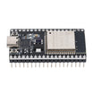
- ESP32 38-Pin Dev Board (CP2102, USB-C) - main microcontroller with Wi-Fi for NTP time sync.
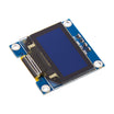
- SSD1306 0.96" I2C OLED - displays time, date, and sensor readings.
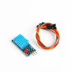
- DHT11 Temperature & Humidity Sensor - reads room temperature and humidity (the original used a DHT22; same library, one constant changes).
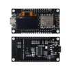
- NodeMCU with Built-in 0.96" OLED - all-in-one alternative for an ESP8266 version.
- 400-Point Breadboard - quick prototyping without soldering.
- Dupont Jumper Wires - wiring for I2C and the DHT data line.
External
- A 2.4 GHz Wi-Fi network
Note: The original project used the NTPClient library and a fixed UTC offset. This version uses the ESP32 core's built-in configTzTime(), which takes a POSIX time-zone string, so daylight-saving changes happen automatically and there is nothing extra to install.
Step-by-Step Guide
Step 1 - Wire the OLED and DHT
Goal: Connect the display and sensor with a minimal wiring setup.
What to do: OLED: VCC to 3V3, GND to GND, SDA to GPIO 21, SCL to GPIO 22. DHT11: VCC to 3V3, GND to GND, DATA to GPIO 23 (the three-pin module has its pull-up resistor built in).
Expected result: A display and a sensor sharing the 3.3 V rail.
Step 2 - Install Libraries and Pick Your Time Zone
Goal: Install the required Arduino libraries and choose a POSIX time-zone string.
What to do: In the Arduino IDE Library Manager, install "Adafruit SSD1306", "Adafruit GFX", and "DHT sensor library" (with its Adafruit Unified Sensor dependency). Then find your POSIX TZ string. Examples: EST5EDT,M3.2.0,M11.1.0 for US Eastern, CET-1CEST,M3.5.0,M10.5.0/3 for Central Europe, GMT0BST,M3.5.0/1,M10.5.0 for the UK.
Expected result: Libraries installed and a TZ string ready to paste into the sketch.
Step 3 - Upload the Sketch
Goal: Compile and upload code that connects to Wi-Fi, syncs NTP time, and displays time plus DHT readings on the OLED.
Code:
#include <WiFi.h>
#include <time.h>
#include <Wire.h>
#include <Adafruit_GFX.h>
#include <Adafruit_SSD1306.h>
#include <DHT.h>

const char* SSID = "YourNetwork";
const char* PASS = "YourPassword";
const char* TZ   = "EST5EDT,M3.2.0,M11.1.0";     // your POSIX time-zone string

Adafruit_SSD1306 oled(128, 64, &Wire, -1);
DHT dht(23, DHT11);                              // change to DHT22 if that's what you have

void setup() {
  Serial.begin(115200);
  Wire.begin(21, 22);
  oled.begin(SSD1306_SWITCHCAPVCC, 0x3C);
  oled.setTextColor(SSD1306_WHITE);
  oled.clearDisplay(); oled.setCursor(0, 0); oled.print("Connecting..."); oled.display();

  WiFi.begin(SSID, PASS);
  while (WiFi.status() != WL_CONNECTED) delay(250);

  configTzTime(TZ, "pool.ntp.org", "time.nist.gov");   // sync clock, apply zone + DST
  dht.begin();
}

void loop() {
  struct tm t;
  if (!getLocalTime(&t)) { delay(500); return; }     // waits for the first NTP sync

  float tempC = dht.readTemperature();
  float hum   = dht.readHumidity();

  char hhmmss[9], date[24];
  strftime(hhmmss, sizeof hhmmss, "%H:%M:%S", &t);
  strftime(date,   sizeof date,   "%a %d %b %Y", &t);

  oled.clearDisplay();
  oled.setTextSize(2); oled.setCursor(16, 0);  oled.print(hhmmss);
  oled.setTextSize(1); oled.setCursor(22, 22); oled.print(date);
  oled.setCursor(0, 44);
  if (isnan(tempC)) oled.print("DHT read error");
  else {
    oled.print("Temp "); oled.print(tempC, 1); oled.print(" C  Hum ");
    oled.print(hum, 0);  oled.print("%");
  }
  oled.display();
  delay(1000);
}
What to do: Fill in your Wi-Fi credentials and your TZ string, upload, and wait a few seconds for the first sync.
Expected result: A large HH:MM:SS readout that updates once a second, the date beneath it, and live temperature/humidity along the bottom.
Step 4 - Understand How Time Sync Works
Goal: Know where the accuracy comes from and what happens if Wi-Fi drops.
What to do: configTzTime() asks an NTP server for the current UTC time, then the ESP32 keeps counting with its own oscillator and re-syncs in the background every hour or so. Between syncs it can drift a fraction of a second, and it never needs a battery. If Wi-Fi is unavailable, the clock keeps running from the last sync.
Expected result: Confidence that this clock stays correct for long periods without manual setting.
Step 5 - Optional Enhancements
Goal: Customize the display and turn the clock into a more polished device.
What to do: Add a 12-hour mode with AM/PM (%I:%M %p), dim the OLED at night with oled.dim(true) based on the hour, or read a potentiometer on GPIO 36 to set brightness the way the original did. You can also publish temperature to MQTT to turn the desk clock into a room sensor node.
Expected result: A clock you can tailor to your space and extend into your next Wi-Fi sensor project.
Conclusion
You built an ESP32 internet clock that uses NTP time, a POSIX time-zone string for automatic DST, an SSD1306 I2C OLED for display, and a DHT sensor for temperature and humidity. These are core building blocks for many connected projects, and this build gives you a practical device you can keep using.
Want the exact parts used in this build? Grab them from ShillehTek.com. If you want help customizing this project or building something for your product, check out our IoT consulting services.
Credits
All photos and images in this tutorial are credited to Marcelo Rovai (MJRoBot) on Hackster.io. The original guide by Marcelo Rovai served as the reference for this ShillehTek version. We thank him for his excellent work in the maker community.




.png?v=25000753014097803521791168436)

.png?v=68677308723310773341791168436)


