

Project Overview
ESP32 Bluetooth Gamepad: Build a wireless BLE HID controller using an ESP32 dev board, a KY-023 dual-axis joystick module, and four tactile buttons so it pairs natively with Android phones and Windows PCs (no app or driver required).
Every phone, laptop, and single-board computer already speaks Bluetooth HID, the same protocol a store-bought wireless controller uses. An ESP32 can speak it too, which means a joystick module, a handful of tactile buttons, and about a hundred lines of code become a controller that pairs like any other.
This guide builds a one-stick, five-button gamepad on a breadboard, pairs it with an Android phone and a Windows PC, calibrates the stick so the cursor does not drift, and shows how to grow it into a two-stick pad, a battery-powered handheld, or the transmitter for your own robot.
- Time: ~1 hour
- Skill level: Beginner to Intermediate
- What you will build: A BLE HID gamepad (X/Y stick + 5 buttons) recognized natively by Android, Windows, macOS, Linux, and Raspberry Pi, with a center-calibrated dead zone and about 100 reports a second.

Parts List
From ShillehTek
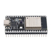
- ESP32 Dev Board (38-pin, CP2102, USB-C) - the BLE HID controller brain
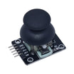
- KY-023 Dual-Axis Analog Joystick Module - X/Y analog input plus stick click
- Tactile Button Kit - four face buttons
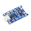
- TP4056 Charging Board - for the battery-powered version
- 400-Point Breadboard - quick prototyping
- Dupont Jumper Wires - easy wiring on the breadboard
External
- An Android phone or a Bluetooth-equipped PC to pair with; a free gamepad tester app or a web gamepad tester in Chrome
- Optional: an 18650 cell and holder for the handheld version
Note: the ESP32's second ADC (GPIO0, 2, 4, 12-15, 25-27) is unusable while the radio is on. Bluetooth is friendlier than Wi-Fi here, but put the joystick on ADC1 pins (GPIO32-39) anyway so the same board works if you ever add Wi-Fi. GPIO34-39 are input-only, which is exactly what an analog stick needs.
Step-by-Step Guide
Step 1 - Wire the stick and buttons

Goal: Two analog axes and five digital inputs.
What to do: KY-023: +5V to 3V3 (the ESP32 ADC must never see 5 V), GND to GND, VRx to GPIO34, VRy to GPIO35, SW to GPIO32.
What to do: Buttons: connect one leg of each to GPIO25, GPIO26, GPIO27, and GPIO14, and connect the other legs to GND. No resistors are needed because the sketch enables internal pull-ups, so pressed reads LOW. Lay the buttons out as a diamond (A/B/X/Y) to the right of the stick.
Expected result: A controller-shaped breadboard. Nothing happens yet.
Step 2 - Install the libraries
Goal: HID without writing descriptors by hand.
What to do: Install the ESP32 board package (Boards Manager, search for "esp32" by Espressif, version 3.x). Then in the Library Manager install NimBLE-Arduino and ESP32-BLE-Gamepad (by lemmingDev). Select your ESP32 Dev Module and the correct port.
Expected result: The sketch below compiles.
Step 3 - Upload the sketch
#include <BleGamepad.h>          // lemmingDev ESP32-BLE-Gamepad (needs NimBLE-Arduino)

const int JOY_X = 34, JOY_Y = 35, JOY_SW = 32;          // KY-023: VRx, VRy, SW
const int BTN[4] = {25, 26, 27, 14};                    // A, B, X, Y  (other leg to GND)
const int DEADZONE = 60;                                // raw ADC counts around centre that count as "still"
int cx = 2048, cy = 2048;                               // stick centre, measured at boot

BleGamepad pad("ShillehTek Pad", "ShillehTek", 100);    // name, manufacturer, battery %

int toAxis(int raw, int centre) {                       // 12-bit ADC reading -> 0..32767 with the centre at 16384
  int d = raw - centre;
  if (abs(d) < DEADZONE) d = 0;
  long v = 16384L + (long)d * 16384L / 2048L;
  return constrain(v, 0, 32767);
}

void setup() {
  pinMode(JOY_SW, INPUT_PULLUP);
  for (int i = 0; i < 4; i++) pinMode(BTN[i], INPUT_PULLUP);
  analogReadResolution(12);
  delay(200);
  cx = analogRead(JOY_X); cy = analogRead(JOY_Y);       // hands off the stick while it boots

  BleGamepadConfiguration cfg;
  cfg.setAutoReport(false);                             // we send exactly one report per loop
  cfg.setControllerType(CONTROLLER_TYPE_GAMEPAD);
  cfg.setButtonCount(5);                                // four buttons + stick click
  cfg.setHatSwitchCount(0);
  cfg.setWhichAxes(true, true, false, false, false, false, false, false);   // X and Y only
  cfg.setAxesMin(0); cfg.setAxesMax(32767);
  pad.begin(&cfg);
}

void loop() {
  if (!pad.isConnected()) { delay(100); return; }       // nothing to do until something pairs

  pad.setX(toAxis(analogRead(JOY_X), cx));
  pad.setY(toAxis(analogRead(JOY_Y), cy));

  for (int i = 0; i < 4; i++) {
    if (digitalRead(BTN[i]) == LOW) pad.press(BUTTON_1 + i); else pad.release(BUTTON_1 + i);
  }
  if (digitalRead(JOY_SW) == LOW) pad.press(BUTTON_5); else pad.release(BUTTON_5);

  pad.sendReport();
  delay(10);                                            // ~100 reports per second
}
What to do: Upload the sketch. Do not touch the stick for the first second because the sketch samples the resting position as the center.
Expected result: The ESP32 advertises itself as "ShillehTek Pad". Nothing visible happens on the board; pairing and testing happen on your phone or PC.
Step 4 - Pair and test
Goal: See your inputs on a screen.
What to do: Android: Settings to Bluetooth to Pair new device, then select "ShillehTek Pad". Open a gamepad tester app and confirm the stick and buttons respond.
What to do: Windows: Settings to Bluetooth to Add device; then run joy.cpl (or use a web gamepad tester in Chrome) to view the axes and buttons. On a Raspberry Pi it shows up in RetroArch input settings like any controller. The ESP32 remembers pairing and reconnects automatically.
Expected result: Axes sit at center when released, reach near full deflection at the edges, and buttons register cleanly.
Step 5 - Tune the feel
Goal: No drift and correct directions.
What to do: If the cursor creeps when you let go, raise DEADZONE to 100 to 150. If up is down, invert Y by using pad.setY(32767 - toAxis(...)).
What to do: If the stick reaches full deflection before the physical stop, the potentiometer may not swing the full 0 to 3.3 V range. Measure your real min and max over Serial and scale to those values instead of assuming 0 to 4095. Lower delay(10) for faster response; 10 ms is already similar to many commercial controllers.
Expected result: A controller that feels stable and predictable instead of drifting like a prototype.
Step 6 - Grow it
Goal: Expand from one stick to a more complete handheld or remote.
What to do: Add a second KY-023 on GPIO36/39 and enable the Z and rZ axes in setWhichAxes() for a twin-stick pad. Enable a hat switch and wire four buttons as a D-pad.
What to do: For battery power, run an 18650 through the TP4056 (cell to TP4056 OUT to ESP32 5V/VIN) and report real battery level with pad.setBatteryLevel(). Or flip the idea: run a BLE central sketch on a second ESP32 in a robot to use this as a custom wireless remote.
Expected result: A flexible BLE controller foundation you can adapt to your project.
Conclusion
This build turns an ESP32 plus a KY-023 joystick and buttons into a BLE HID gamepad that pairs with standard Bluetooth menus and works across Android, Windows, macOS, Linux, and Raspberry Pi. With a simple center calibration and a dead zone, you get stable analog control without drift.
Want the exact parts used in this build? Grab them from ShillehTek.com. If you want help customizing this project or building something for your product, check out our IoT consulting services.
Photo credit: All photos and images in this tutorial are credited to Ernst Sikora on Hackster.io. The original guide by Ernst Sikora served as the reference for this ShillehTek version.




.png?v=25000753014097803521791168436)

.png?v=68677308723310773341791168436)


