

Project Overview
ESP32 Capacitive Touch Pins: In this build, you will use the ESP32 capacitive touch pins (T0 to T9) as a no-moving-parts button made from bare wire or foil, then use that same touch pad to toggle an LED or relay and wake the ESP32 from deep sleep.
The original ESP32 has ten touch-sensing inputs built into the chip. Connect a bare wire, a screw head, or a strip of copper tape and it becomes a button. Reading touchRead() tells you when a finger is near. This guide calibrates a touch pad automatically, turns it into a reliable toggle for an LED or relay, and then uses the same pad to wake the board from deep sleep for battery-powered projects.
- Time: ~30 minutes
- Skill level: Beginner to Intermediate
- What you will build: A self-calibrating touch button that toggles an output, plus a touch-to-wake deep sleep demo.

Parts List
From ShillehTek
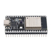
- ESP32 38-Pin Dev Board (CP2102, USB-C) - the classic ESP32 has touch pins T0 to T9
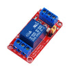
- 1-Channel 5V Relay Module - for a touch-controlled lamp in Step 4
- Resistor Kit - 220Ω for an indicator LED
- 400-Point Breadboard - quick prototyping for the touch pad and LED/relay wiring
- Dupont Jumper Wires - for connecting the touch pin and output wiring
External
- A touch pad: a jumper wire, a coin, a screw, or copper/aluminum foil tape
Note: Touch pins are on the original ESP32 (this board) and on the ESP32-S2/S3. The ESP32-C3 and C6 do not have them. On the classic ESP32 the reading drops when touched (idle ~70, touched ~20); on S2/S3 it rises instead. The calibration approach below is designed to handle either behavior.
Step-by-Step Guide
Step 1 - Make a Touch Pad
Goal: Create something you can touch on T0.
What to do: Plug a jumper wire into GPIO 4 (touch channel T0) and leave the other end bare, or tape it to a coin or a square of foil to make a larger touch pad.
Wire an LED from GPIO 2 (the onboard LED works too) through a 220Ω resistor to GND.
Expected result: A touch pad on T0 and an indicator LED output wired to the ESP32.
Step 2 - See the Raw Numbers
Goal: Understand what a touch looks like in the raw touchRead() values.
What to do: Upload a sketch that prints touchRead(T0) ten times a second and open the Serial Plotter. Touch the wire and observe how the value changes, then releases back to its idle level.
Bigger pads and longer wires can change the idle value, which is why the next step calibrates automatically.
Expected result: A clear difference between idle and touched readings in the Serial Plotter.
Step 3 - The Sketch: Self-Calibrating Toggle
Goal: Toggle an output once per touch using an automatically measured baseline and simple debounce.
Code:
const int PAD = T0;            // GPIO 4
const int LED = 2;             // later: relay IN
int baseline = 0;              // idle reading measured at boot
bool state = false, wasTouched = false;
unsigned long lastToggle = 0;

int readPad() {                // average a few samples to kill jitter
  long sum = 0;
  for (int i = 0; i < 8; i++) sum += touchRead(PAD);
  return sum / 8;
}

bool touched() {
  int v = readPad();
  return v < baseline * 0.6;   // classic ESP32: value drops when touched
  // ESP32-S2/S3: use  v > baseline * 1.4  instead (value rises)
}

void setup() {
  Serial.begin(115200);
  pinMode(LED, OUTPUT);
  delay(300);
  baseline = readPad();        // don't touch the pad while booting
  Serial.printf("baseline %d\n", baseline);
}

void loop() {
  bool now = touched();
  if (now && !wasTouched && millis() - lastToggle > 250) {   // rising edge + debounce
    state = !state;
    digitalWrite(LED, state);
    lastToggle = millis();
    Serial.println(state ? "ON" : "OFF");
  }
  wasTouched = now;
  delay(20);
}
What to do: Upload with your hands away from the pad, then tap the pad.
Expected result: Each tap toggles the LED once (no bounce, no double-triggers). If you change pad size, reset the board to recalibrate.
Step 4 - Touch-Controlled Lamp
Goal: Use the touch toggle to switch a real load with a relay module.
What to do: Move the output signal to the relay module IN pin. Wire VCC to 5V VIN and GND to GND. If your relay module is active-LOW, invert the logic in your code.
Hide the foil pad under a thin plastic or wooden panel. Capacitive sensing can work through about a millimeter or two of non-metal material.
Expected result: A lamp (or other relay-controlled load) switches when you tap the touch area.
Step 5 - Wake from Deep Sleep with a Touch
Goal: Use the touch pad as a wake-up source from deep sleep for low-power battery projects.
What to do: The touch controller keeps running in deep sleep. Replace your normal loop() behavior with this pattern: blink to say hello, arm the touch wake-up, then sleep.
Code:
#define THRESHOLD 40                        // a bit above your "touched" reading
void onTouch() {}                           // required, can be empty

void setup() {
  pinMode(2, OUTPUT);
  for (int i = 0; i < 3; i++) { digitalWrite(2, HIGH); delay(100); digitalWrite(2, LOW); delay(100); }
  touchAttachInterrupt(T0, onTouch, THRESHOLD);
  esp_sleep_enable_touchpad_wakeup();
  esp_deep_sleep_start();                   // ~10 uA until the pad is touched
}
void loop() {}
Expected result: The board blinks, sleeps, and wakes to blink again every time you touch the pad.
Conclusion
You built an ESP32 capacitive touch button using a simple wire or foil pad, then used it to toggle an LED or relay with automatic baseline calibration. You also configured the ESP32 to wake from deep sleep using the touch pad for a low-power, battery-friendly interface.
Want the exact parts used in this build? Grab them from ShillehTek.com. If you want help customizing this project or building something for your product, check out our IoT consulting services.
Credits
All photos and images in this tutorial are credited to Marcelo Rovai (MJRoBot) on Hackster.io. The original guide by Marcelo Rovai served as the reference for this ShillehTek version. We thank him for his excellent work in the maker community.





.png?v=25000753014097803521791168436)

.png?v=68677308723310773341791168436)


