

Project Overview
ESP32-CAM + OV2640 camera: Build a WiFi surveillance robot car you can drive from your phone with live video streaming, pan/tilt aiming, and full motor control using an L298N motor driver.
Send it to the kitchen to check whether you left the kettle on.
- Time: An afternoon
- Skill level: Intermediate
- What you will build: A phone-controlled rover with a streaming camera head on a pan/tilt mount, driven by an ESP32-CAM and an L298N motor driver.

Parts List
From ShillehTek
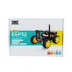
- ESP32-CAM 4WD Smart Robot Car Kit with WiFi App Control - the all-in-one route: camera board, chassis, motors, and app firmware in one box
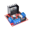
- L298N Motor Driver Board (for the DIY build shown here)
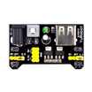
- MB102 Breadboard Power Supply Module - clean 5V for the camera and servo
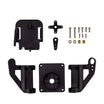
- Pan-Tilt Servo Bracket Kit (SG90/MG90S) - aim the camera without moving the robot
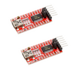
- FT232RL USB-to-TTL Serial Adapter - the ESP32-CAM has no USB port; this flashes it
- Dupont Jumper Wires
External
- Robot chassis with two DC gear motors and wheels (or use the 4WD kit above)
- SG90 micro servo for the pan mount
- Battery pack (Li-ion cells or AA holder) for the motor supply
- Double-sided mounting tape and a small piece of foam
Note: The ESP32-CAM module itself runs about $10 - a camera, WiFi radio, and dual-core micro in one thumb-sized board. It's the entire brain of this robot.
Step-by-Step Guide
Step 1 - Meet the ESP32-CAM
Goal: Understand the board doing all the work.
What to do: The ESP32-CAM pairs an ESP32-S with an OV2640 camera and a handful of spare GPIOs - enough to stream video and drive a motor controller at the same time. It's programmed from the Arduino IDE, with one quirk: no onboard USB, so a serial adapter does the flashing.

Expected result: You know the architecture: one board streams video and drives the robot.
Step 2 - Assemble the Chassis
Goal: Build the rolling platform.

What to do: Mount the two DC gear motors and wheels on the chassis (a caster makes the third wheel), then bolt the L298N motor driver onto the platform.


Expected result: A drivable platform with a pan/tilt head waiting for its camera.
Step 3 - Power It Right with the MB102
Goal: Give the ESP32-CAM and servo a clean 5V rail.
What to do: You can steal 5V from the L298N's regulator, but a dedicated MB102 power module is far more convenient - it adds a power button and flexible wiring. Trim the pins on its underside and stick it to the chassis with double-sided mounting tape.


Expected result: Reliable power - the #1 cause of ESP32-CAM brownouts, solved.
Step 4 - Wire Everything
Goal: Connect camera board, motor driver, servo, and power.
What to do: Follow the schematic: ESP32-CAM GPIOs to the L298N inputs (two per motor for direction, plus enable pins), the servo signal to a spare GPIO, motor battery into the L298N, and the MB102's 5V to the ESP32-CAM and servo. Mount the camera to the pan/tilt head with foam and tape.


Expected result: Hardware complete.
Step 5 - Flash the Firmware
Goal: Upload the robot sketch through the FT232RL.
What to do: Install the ESP32 board package in the Arduino IDE, open the robot sketch (grab it from the original project page's code download), and drop in your network credentials:
Code:
const char* ssid     = "Your_WIFI_Network";
const char* password = "Your_WIFI_Password";
Wire the FT232RL to the ESP32-CAM per the diagram, and the critical detail: GPIO 0 to GND puts the board in flashing mode. Press the onboard RST button, then hit Upload.


Expected result: Sketch flashed. Disconnect GPIO 0 from GND afterward.
Step 6 - Get the IP and Drive
Goal: Connect the app and take the wheel.
What to do: Open the Serial Monitor at 115200, press RST, and note the IP address the board prints. Reconnect the camera to the robot, power up, and point the companion app (linked on the original project page) at that IP. Live video should appear with drive and pan controls.


Expected result: A WiFi rover streaming live video, driven from your phone. Prefer to skip the chassis work? The ShillehTek 4WD kit ships the drivetrain and app-ready firmware out of the box.
Conclusion
With an ESP32-CAM (OV2640 camera), an L298N motor driver, and a pan/tilt mount, you built a WiFi surveillance robot car that streams live video and drives from your phone while letting you aim the camera independently of the wheels.
Want the exact parts used in this build? Grab them from ShillehTek.com. If you want help customizing this project or building something similar for your product, check out our IoT consulting services.
Credit: Photos and images in this tutorial are credited to KDPA on Hackster.io. The original guide by KDPA served as the reference for this ShillehTek version.



.png?v=25000753014097803521791168436)

.png?v=68677308723310773341791168436)


