

Project Overview
ESP32-C6 Zigbee light and switch: Use two ESP32-C6 boards with their native IEEE 802.15.4 radio to build a real Zigbee network where a wireless switch toggles a remote LED light.
The ESP32-C6 is special: alongside WiFi 6 and BLE it includes an 802.15.4 radio, which means it can run Zigbee without an external module. In this project you flash two C6 boards: one becomes a Zigbee light (end device) and the other becomes a Zigbee switch (coordinator). Press the switch board button and the light board LED toggles over the Zigbee network you created.
- Time: 1 to 2 hours
- Skill level: Intermediate
- What you will build: A two-node Zigbee network (wireless light and switch) using only ESP32-C6 boards and the Arduino IDE.

Parts List
From ShillehTek
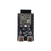
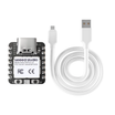
- ESP32-C6-N4 Pre-Soldered Development Board x 2 (the original uses a Beetle C6 Mini; any ESP32-C6 board works; the XIAO ESP32-C6 is a compact alternative)
- Metal Film Resistor Kit (one 220 ohm resistor for the LED)
- 400-Point Breadboard and jumper wires (for quick prototyping)
External
- One LED and two USB cables
Note: Zigbee mesh networking, low power, AES-128 security, and large network size are enabled by the ESP32-C6 802.15.4 radio. No extra Zigbee module is required.
Step-by-Step Guide
Step 1 - Set up the Arduino IDE for the C6
Goal: Get ESP32-C6 and Zigbee build support installed.
What to do: In the Arduino IDE, add the Espressif board manager URL in Preferences:
https://raw.githubusercontent.com/espressif/arduino-esp32/gh-pages/package_esp32_index.jsonInstall the esp32 package, then select your board (for example, ESP32C6 Dev Module or your specific ESP32-C6 variant). You should now see Zigbee examples under File > Examples > Zigbee.
Expected result: ESP32-C6 boards are selectable and Zigbee examples are visible.
Step 2 - Wire the light node
Goal: Connect one LED to GPIO4.
What to do: On the board that will be the light, connect an LED through a 220 ohm resistor from GPIO4 to GND. The BOOT button on the board doubles as the factory-reset and local toggle control, so no extra button wiring is required.
Expected result: Light node hardware is complete (an LED and resistor on GPIO4).
Step 3 - Flash the Zigbee light (end device)
Goal: Make board #1 behave like a Zigbee light bulb.
What to do: Set these critical Arduino IDE options for the light board:
- Zigbee Mode: Zigbee ED (end device)
- Partition Scheme: Zigbee 4MB with spiffs
Upload the light sketch from the Espressif Zigbee examples (Apache 2.0). The core of it is shown below.
#ifndef ZIGBEE_MODE_ED
#error "Zigbee end device mode is not selected in Tools->Zigbee mode"
#endif
#include "Zigbee.h"

#define ZIGBEE_LIGHT_ENDPOINT 10
uint8_t led = 4;
uint8_t button = BOOT_PIN;
ZigbeeLight zbLight = ZigbeeLight(ZIGBEE_LIGHT_ENDPOINT);

void setLED(bool value) {
  digitalWrite(led, value);
}

void setup() {
  Serial.begin(115200);
  pinMode(led, OUTPUT);
  digitalWrite(led, LOW);
  pinMode(button, INPUT_PULLUP);

  zbLight.setManufacturerAndModel("Espressif", "ZBLightBulb");
  zbLight.onLightChange(setLED);   // callback drives the LED

  Serial.println("Adding ZigbeeLight endpoint to Zigbee Core");
  Zigbee.addEndpoint(&zbLight);

  if (!Zigbee.begin()) {           // starts as an end device
    Serial.println("Zigbee failed to start! Rebooting...");
    ESP.restart();
  }
  Serial.println("Connecting to network");
  while (!Zigbee.connected()) {
    Serial.print(".");
    delay(100);
  }
  Serial.println();
}

void loop() {
  // Hold BOOT 3s = Zigbee factory reset; quick press = local toggle
  if (digitalRead(button) == LOW) {
    delay(100);
    int startTime = millis();
    while (digitalRead(button) == LOW) {
      delay(50);
      if ((millis() - startTime) > 3000) {
        Serial.println("Resetting Zigbee to factory and rebooting in 1s.");
        delay(1000);
        Zigbee.factoryReset();
      }
    }
    zbLight.setLight(!zbLight.getLightState());
  }
  delay(100);
}
Expected result: The light boots and prints dots in Serial while it waits to join a Zigbee network.
Step 4 - Flash the Zigbee switch (coordinator)
Goal: Make board #2 form the Zigbee network and control the light.
What to do: Switch the Arduino IDE settings for the second board to:
- Zigbee Mode: Zigbee ZCZR (coordinator/router)
- Partition Scheme: Zigbee 4MB with spiffs
Upload the switch sketch from the Zigbee examples. Key behaviors to confirm from the sketch:
- It creates a
ZigbeeSwitchendpoint and starts asZIGBEE_COORDINATOR. - It opens the network for joining for 180 seconds after boot using
Zigbee.setRebootOpenNetwork(180). - It waits until a light binds, then prints the light short address, IEEE address, manufacturer, and model.
- The BOOT button uses an interrupt with a FreeRTOS queue, and each debounced press calls
zbSwitch.lightToggle(). - It re-lists bound devices every 10 seconds.
Expected result: The switch boots, forms the network, and reports when the light joins and binds.
Step 5 - Watch the network form, then toggle
Goal: Verify network formation, binding, and wireless control.
What to do: Power both boards, with the switch board first. The light should join during the 180-second open-network window (its Serial dots stop). The switch prints the bound device addresses when binding completes.
Press the BOOT button on the switch board. The LED on the light board should toggle wirelessly via a Zigbee toggle command. Discovery uses the Zigbee Device Object Match Descriptor Request, the same mechanism commercial hubs use.
Expected result: Pressing a button on one ESP32-C6 toggles an LED on the other through Zigbee.
Step 6 - Where to take it
Goal: Extend the two-node demo into a larger system.
What to do: The switch sketch already calls allowMultipleBinding(true), so more lights can bind to one switch. You can also swap the LED endpoint for a relay, add ESP32-C6 sensor nodes (temperature, occupancy), or join your devices to an existing Zigbee hub ecosystem.
Expected result: You have a clear path from a simple light and switch to a multi-device Zigbee setup.
Conclusion
You used the ESP32-C6 native 802.15.4 radio to build a working Zigbee light and switch pair, including the correct Arduino IDE Zigbee modes (ED vs ZCZR), Zigbee partition scheme, endpoint registration, network formation, binding, and wireless toggling.
Want the exact parts used in this build? Grab them from ShillehTek.com. If you want help customizing this project or building something for your product, check out our IoT consulting services.
Credits: Photos and reference credited to Hackster.io. Sketches are based on Espressif Systems Zigbee examples under Apache 2.0 (with Jan Prochazka), referenced via the original guide by Nickson Kiprotich.





.png?v=25000753014097803521791168436)

.png?v=68677308723310773341791168436)


