

Project Overview
ESP32-C6 Temperature Logger with DHT11 + OLED: Build an ESP32-C6 temperature and humidity logger using a DHT11 sensor and an SSD1306 OLED to show centered, live readings on-screen.
This pocket-sized monitor also prints debug output over Serial, and it is a great starting point for future WiFi 6, BLE, Thread, Zigbee, and Matter integrations on the same chip.
- Time: ~1 hour
- Skill level: Beginner-Intermediate
- What you will build: A compact temp/humidity display with centered OLED readouts, serial debug output, and a clear path to Matter/Thread smart-home integration.

Parts List
From ShillehTek
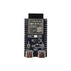
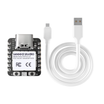
- ESP32-C6-N4 Pre-Soldered Development Board - main microcontroller board for reading the sensor and driving the OLED (or the ultra-compact Seeed XIAO ESP32-C6 for the smallest possible build)
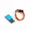
- DHT11 Temperature & Humidity Sensor (with Cables) - measures temperature and humidity
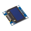
- SSD1306 0.96" I2C White OLED Display - shows live readings on a 128x64 display
- 400-Point Breadboard - quick, solder-free prototyping
- Dupont Jumper Wires - wiring the DHT11 and OLED to the ESP32-C6
External
- USB-C cable for programming and serial debugging
- Optional: a 3D-printed enclosure for a finished desk gadget
Note: The ESP32-C6 supports WiFi 6, BLE 5, Thread, Zigbee, and Matter, so this logger can later become a full smart-home sensor without changing boards. Want tighter accuracy? Swap the DHT11 for a DHT22 or an ENS160 air-quality sensor; the C6 can handle several sensors at once.
Step-by-Step Guide
Step 1 - Wire the Sensor and Display
Goal: Three connections for the DHT11, four for the OLED.
What to do: Wire the DHT11 as VCC to 3.3V, GND to GND, and DATA to GPIO2. Wire the OLED as VCC to 3.3V, GND to GND, plus SDA and SCL to your board's I2C pins.
The SSD1306 display uses I2C address 0x3C with a 128x64 resolution, and both values are used in the code in Step 2.

Expected result: Sensor and display are wired for 3.3V operation.
Step 2 - Upload the Code
Goal: Read the DHT11 and print centered values on the OLED.
What to do: Install Adafruit GFX, Adafruit SSD1306, and the DHT sensor library. Select your ESP32-C6 board in the Arduino IDE, then upload this sketch:
Code:
#include <Wire.h>
#include <Adafruit_GFX.h>
#include <Adafruit_SSD1306.h>
#include "DHT.h"

#define SCREEN_WIDTH 128
#define SCREEN_HEIGHT 64
#define OLED_RESET -1
Adafruit_SSD1306 display(SCREEN_WIDTH, SCREEN_HEIGHT, &Wire, OLED_RESET);

#define DHTPIN 2          // DHT11 data pin (match your wiring)
#define DHTTYPE DHT11
DHT dht(DHTPIN, DHTTYPE);

void setup() {
  Serial.begin(115200);
  dht.begin();
  display.begin(SSD1306_SWITCHCAPVCC, 0x3C);
  display.setTextSize(2);
  display.setTextColor(SSD1306_WHITE);
}

void loop() {
  float t = dht.readTemperature();
  float h = dht.readHumidity();
  Serial.printf("T: %.1f C  H: %.0f %%\n", t, h);

  display.clearDisplay();

  // center each line using its measured pixel width
  String tempStr = "T:" + String(t, 1) + "C";
  int16_t x1, y1; uint16_t w, hgt;
  display.getTextBounds(tempStr, 0, 0, &x1, &y1, &w, &hgt);
  display.setCursor((SCREEN_WIDTH - w) / 2, 15);
  display.print(tempStr);

  String humStr = "H:" + String(h, 0) + "%";
  display.getTextBounds(humStr, 0, 0, &x1, &y1, &w, &hgt);
  display.setCursor((SCREEN_WIDTH - w) / 2, 40);
  display.print(humStr);

  display.display();
  delay(2000);          // update every 2 s
}
Expected result: Temperature and humidity refresh every two seconds, centered on the OLED, with debug lines in the Serial Monitor.

Step 3 - Why Centered Text Matters
Goal: Make the readout look intentional, not accidental.
What to do: If your display sits behind a case cutout with wide borders, left-aligned text can look off-center through the window. getTextBounds() returns the pixel width of any string, so the sketch computes (SCREEN_WIDTH - w) / 2 each time the value changes.
Expected result: The readout stays visually balanced as values change width (for example, 23.4C vs 9.8C).
Step 4 - Box It Up
Goal: Turn the breadboard build into a desk gadget.
What to do: Use a small 3D-printed enclosure with a display cutout. For small boards, measure your ESP32-C6 and OLED before modeling so the cutouts fit cleanly, or start from existing enclosure files and adapt the openings.

Expected result: A self-contained temperature logger that looks polished.
Step 5 - Where to Take It
Goal: Plan upgrades that use the ESP32-C6 radios.
What to do: The same board can push readings to a cloud dashboard over WiFi 6, advertise them over BLE, or join a Matter/Thread network as a smart-home sensor. Add deep sleep between readings to extend runtime on a small battery.
Expected result: A clear upgrade path from desk gadget to connected sensor.
Conclusion
You built an ESP32-C6 temperature logger that reads a DHT11 sensor and shows centered temperature and humidity values on an SSD1306 OLED, with Serial output for debugging and an enclosure-ready layout.
Want the exact parts used in this build? Grab them from ShillehTek.com. If you want help customizing this project or building something for your product, check out our IoT consulting services.
Credits
All photos and images in this tutorial are credited to Pradeep on Hackster.io. The original guide by Pradeep served as the reference for this ShillehTek version. We thank him for his excellent work in the maker community.




.png?v=25000753014097803521791168436)

.png?v=68677308723310773341791168436)


