Project Overview
ESP32-C3 + FS90R servos: build a palm-sized Wi-Fi joystick robot using an ESP32-C3 dev board and two FS90R continuous-rotation micro servos, controlled from any phone browser with no app, router, or separate motor driver.
A 170-point mini breadboard becomes the chassis. The ESP32-C3 runs its own Wi-Fi network and serves a simple joystick page. The joystick commands are mixed into two servo signals for steering, and a failsafe stops the robot if the connection drops.
- Time: about 1.5 hours
- Skill level: Beginner
- What you will build: A palm-sized two-wheel robot you drive from any phone over Wi-Fi, with a failsafe that stops it if the connection drops.

Parts List
From ShillehTek
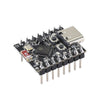
- ESP32-C3 4MB pre-soldered Wi-Fi dev board - runs the Wi-Fi access point, web joystick, and servo control
- FS90R 360-degree continuous rotation micro servo (x2) - drive wheels (left and right)
- SYB-170 170-point mini solderless breadboard - acts as the robot chassis and wiring hub
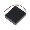
- 4xAA battery holder with switch - robot power with a convenient on/off switch
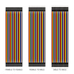
- Dupont jumper wires - signal jumpers; use appropriately rated wiring for the servo power branches
External
- Two wheels that fit the FS90R output spline
- Four AA NiMH rechargeable cells
- Double-sided foam tape or hot glue
- A smooth skid for the third contact point: a large bead, a furniture glide or a small ball caster
- A phone or laptop with a web browser
- Two insulated power distribution connectors, each with enough terminals for the connections below, and wire/connectors rated for the combined servo starting/stall current
- A regulated 5 V buck-boost supply for the ESP32-C3, specified for the four-cell NiMH pack voltage range and the controller’s Wi-Fi current peaks
- A multimeter for polarity, continuity and supply checks
Note: The FS90R is rated for 4.8 to 6 V. Four NiMH cells give about 4.8 V; four fresh alkaline cells measure around 6.4 V, a little above that rating. Before connecting USB, switch the battery off and disconnect the regulator’s 5 V lead from the controller, so the two supplies cannot feed each other.
Step-by-Step Guide
Step 1 - Build the chassis
Goal: Turn the mini breadboard into a rigid two-wheel base.
What to do: Stick one FS90R to each side of the breadboard's underside with foam tape or hot glue, output shafts pointing outwards and lined up with each other. Press the wheels on.
Glue the skid under the opposite end so the robot rests on three points. Fix the battery holder and insulated power connectors on top of or behind the breadboard, keeping the switch reachable. Mount the ESP32-C3 so its header pins remain accessible. Only insert it across the center gap if its header spacing fits and no unintended pins share a connected row; otherwise mount it beside the board and use signal jumpers.
The servos face opposite directions, so "forward" on one is "backward" on the other; the sketch handles that.
Expected result: A small robot that sits level on two wheels and a skid, with the breadboard holes free for wiring.
Step 2 - Wire the servos and battery
Goal: Make separate positive and ground junctions without assuming the mini breadboard has power rails.
What to do: Disconnect USB and switch the battery off before wiring. The SYB-170 has 17 numbered rows: within each row, A–E are one connected five-hole group and F–J are another. The center gap separates those groups; adjacent numbered rows are not connected. There are no long +/− power rails. Check these connections with an unpowered continuity test. See Adafruit’s breadboard guide, “Tiny Breadboard”.
Use two separate insulated distribution connectors for servo power. Route servo supply current through the rated connectors and wire, rather than through the SYB-170 or the ESP32-C3 board:
- Positive junction: battery holder red, both servo red leads, and the regulated 5 V supply’s input-positive lead.
- Ground junction: battery holder black, both servo brown leads, regulator ground, and ESP32-C3 GND.
- Controller supply: regulator 5 V output to the ESP32-C3’s labeled 5V input. Measure the output before connecting the controller. Keep USB disconnected when this supply is connected.
- Left servo signal (orange): GPIO4.
- Right servo signal (orange): GPIO5.
Use the mini breadboard only for convenient signal junctions. For example, A1 and B1 can join two ends of the left signal; A2 and B2 can join the right signal. Keep those two numbered rows separate. These are example free rows, not fixed positions under the controller.
Confirm polarity and that the positive and ground junctions are not shorted. The servos share the battery supply, while the regulator supplies the controller. Check the pack remains within the servos’ 4.8–6 V operating range. GPIO4 and GPIO5 avoid the ESP32-C3 strapping pins GPIO2, GPIO8 and GPIO9.
Expected result: After uploading Step 4, disconnect USB, lift the wheels clear of the bench, and turn on the battery. The controller starts and sends the stop pulses. A servo may need the neutral adjustment in Step 6 before it remains completely still.
Step 3 - Prepare the Arduino IDE
Goal: Get the ESP32 board package ready.
What to do: Install esp32 by Espressif Systems (version 3.x) from the Boards Manager, select ESP32C3 Dev Module, and set USB CDC On Boot to Enabled so the Serial Monitor works over the board's USB port. Switch the battery off and disconnect the regulator’s 5 V lead from the controller before plugging in USB.
Expected result: The board appears as a serial port and accepts uploads.
Step 4 - Upload the robot sketch
Goal: Run the access point, the joystick page and the servo mixer.
What to do: Upload the sketch below. It starts a Wi-Fi access point, serves a joystick page from flash, and turns each joystick position into two servo pulses. Forward stick (y) drives both wheels; sideways stick (x) speeds one up and slows the other, which steers.
Each wheel's command starts just past the servo's dead band, so even a small stick movement turns the wheels. The servo pulses come from the LEDC peripheral at 50 Hz with 14-bit resolution, about 1.2 microseconds per step. If no command arrives for 600 ms, the robot stops.
Code:
// ShillehTek BreadboardBot: ESP32-C3 + two FS90R servos on a 170-point breadboard,
// driven from a phone joystick over the robot's own Wi-Fi access point
#include <WiFi.h>
#include <WebServer.h>

const char *AP_SSID = "BreadboardBot";
const char *AP_PASS = "breadboard";          // at least 8 characters
const int LEFT_PIN = 4;                      // left servo signal
const int RIGHT_PIN = 5;                     // right servo signal
const int STOP_L_US = 1500;                  // trim these if a wheel creeps at stop
const int STOP_R_US = 1500;
const int DEAD_US = 30;                      // FS90R dead band: smallest offset that turns a wheel
const int RANGE_US = 200;                    // offset for full speed
const bool LEFT_REVERSED = false;            // the servos face opposite ways,
const bool RIGHT_REVERSED = true;            // so one of them runs mirrored
const unsigned long FAILSAFE_MS = 600;       // stop if the phone goes quiet

WebServer server(80);
unsigned long lastCmd = 0;
int cmdX = 0, cmdY = 0;

const char PAGE[] = R"rawliteral(<!DOCTYPE html><html><head>
<meta name="viewport" content="width=device-width,initial-scale=1,user-scalable=no">
<title>BreadboardBot</title>
<style>
body{margin:0;background:#111;color:#eee;font-family:sans-serif;text-align:center;touch-action:none}
#pad{width:260px;height:260px;margin:30px auto;border-radius:50%;background:#222;border:2px solid #444;position:relative}
#knob{width:90px;height:90px;border-radius:50%;background:#e33;position:absolute;left:85px;top:85px}
</style></head><body>
<h2>BreadboardBot</h2><div id="pad"><div id="knob"></div></div><p id="s">x 0 y 0</p>
<script>
const pad=document.getElementById('pad'),knob=document.getElementById('knob'),s=document.getElementById('s');
const R=85;let x=0,y=0,active=false;
function show(dx,dy){knob.style.left=(85+dx)+'px';knob.style.top=(85+dy)+'px';s.textContent='x '+x+' y '+y;}
function move(e){const r=pad.getBoundingClientRect();let dx=e.clientX-r.left-130,dy=e.clientY-r.top-130;
const d=Math.hypot(dx,dy);if(d>R){dx=dx*R/d;dy=dy*R/d;}
x=Math.round(dx/R*100);y=Math.round(-dy/R*100);show(dx,dy);}
function send(){fetch('/drive?x='+x+'&y='+y).catch(()=>{});}
pad.addEventListener('pointerdown',e=>{active=true;pad.setPointerCapture(e.pointerId);move(e);send();});
pad.addEventListener('pointermove',e=>{if(active)move(e);});
function release(){active=false;x=0;y=0;show(0,0);send();}
pad.addEventListener('pointerup',release);pad.addEventListener('pointercancel',release);
setInterval(()=>{if(active)send();},100);
</script></body></html>)rawliteral";

uint32_t usToDuty(int us) {                  // 14-bit duty at 50 Hz: 20000 us = 16384 counts
  return ((uint32_t)us * 16384UL + 10000UL) / 20000UL;   // rounded to the nearest count
}

void writeServo(int pin, int stopUs, bool reversed, int pct) {   // pct = -100..100
  pct = constrain(pct, -100, 100);
  if (reversed) pct = -pct;
  int us = stopUs;
  if (pct != 0) us = stopUs + (pct > 0 ? 1 : -1) * (DEAD_US + abs(pct) * (RANGE_US - DEAD_US) / 100);
  ledcWrite(pin, usToDuty(us));
}

void mixAndDrive(int x, int y) {             // arcade mixing: y = forward, x = turn
  if (abs(x) < 8) x = 0;                     // small dead zone around the stick centre
  if (abs(y) < 8) y = 0;
  int left = y + x;
  int right = y - x;
  int biggest = max(abs(left), abs(right));
  if (biggest > 100) {
    left = left * 100 / biggest;
    right = right * 100 / biggest;
  }
  writeServo(LEFT_PIN, STOP_L_US, LEFT_REVERSED, left);
  writeServo(RIGHT_PIN, STOP_R_US, RIGHT_REVERSED, right);
}

void handleDrive() {
  long x = server.arg("x").toInt();
  long y = server.arg("y").toInt();
  cmdX = constrain(x, -100, 100);
  cmdY = constrain(y, -100, 100);
  lastCmd = millis();
  mixAndDrive(cmdX, cmdY);
  server.send(200, "text/plain", "ok");
}

void setup() {
  Serial.begin(115200);
  ledcAttach(LEFT_PIN, 50, 14);
  ledcAttach(RIGHT_PIN, 50, 14);
  mixAndDrive(0, 0);
  WiFi.softAP(AP_SSID, AP_PASS);
  Serial.print("Join Wi-Fi \"BreadboardBot\" and open http://");
  Serial.println(WiFi.softAPIP());
  server.on("/", []() { server.send(200, "text/html", PAGE); });
  server.on("/drive", handleDrive);
  server.begin();
}

void loop() {
  server.handleClient();
  if ((cmdX || cmdY) && millis() - lastCmd > FAILSAFE_MS) {   // phone went quiet: stop
    cmdX = cmdY = 0;
    mixAndDrive(0, 0);
  }
}
Expected result: The Serial Monitor prints the network name and the address http://192.168.4.1.
Step 5 - Drive it from your phone
Goal: Connect and take the first test drive.
What to do: Unplug USB, reconnect the regulator’s 5 V lead with the battery still off, switch the battery on, and join the BreadboardBot network on your phone (password breadboard). Open http://192.168.4.1 and drag the red knob: up drives forward, down reverses, left and right steer, and letting go stops.
The page sends the stick position ten times per second while you hold it.
Expected result: The robot follows the joystick and stops as soon as you lift your finger.
Step 6 - Trim the wheels
Goal: Make it stop cleanly and drive straight.
What to do: Adjust the constants at the top of the sketch:
- STOP_L_US and STOP_R_US: If a wheel creeps when the stick is centred, change its value in 5 microsecond steps. Some FS90R units also have a small trim hole for the stop point.
- LEFT_REVERSED and RIGHT_REVERSED: If one wheel turns backwards when you push forward, flip its flag.
- DEAD_US: Raise it if small stick movements do nothing, lower it if the robot jumps forward.
- RANGE_US: Lower it for a gentler top speed.
Expected result: The robot stays put with the stick centred and tracks straight with the stick pushed fully forward.
Step 7 - Add sensors
Goal: Take it further, like the original BreadboardBot.
What to do: Use any remaining isolated terminal groups for sensor signals. Add sensors only after checking their supply, logic levels and physical fit, then mix their readings into mixAndDrive(). Keep 5 V sensor outputs away from the ESP32-C3’s 3.3 V inputs unless an appropriate level converter is fitted.
Expected result: A robot that can drive itself as well as take orders from your phone.
Conclusion
You built BreadboardBot: an ESP32-C3 on a 170-point mini breadboard driving two FS90R continuous-rotation servos, powered by a 4xAA pack, and controlled from a phone joystick over the robot's own Wi-Fi network with arcade mixing, dead-band compensation, and a connection failsafe.
Want the exact parts used in this build? Grab them from ShillehTek.com. If you want help customizing this project or building something for your product, check out our IoT consulting services.
Credits
All photos and images in this tutorial are credited to Konstantin T (konstantint) on Hackster.io (MIT license). The original guide by Konstantin T served as the reference for this ShillehTek version. We thank them for their excellent work in the maker community.