

Project Overview
ESP32 + ArduinoOTA: This project adds the ArduinoOTA library to an ESP32 sketch so you can upload new firmware over Wi-Fi from the Arduino IDE, without reconnecting a USB cable.
Once a project is installed in a wall, attic, or sealed enclosure, OTA (over-the-air) updates let the Arduino IDE send a new sketch across your network. The ESP32 appears as a network port next to your USB ports, and you can protect uploads with a password while watching progress in the Serial Monitor.
- Time: ~30 minutes
- Skill level: Intermediate
- What you will build: An OTA-enabled ESP32 with a hostname, a password, and upload progress reporting.

Parts List
From ShillehTek
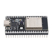
- ESP32 38-Pin Dev Board (CP2102, USB-C) - the target board for ArduinoOTA Wi-Fi uploads
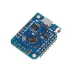
- ESP8266 D1 Mini - can use the same ArduinoOTA approach with a couple include changes
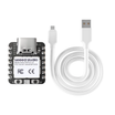
- XIAO ESP32-C6 - OTA is especially helpful on compact boards
- 400-Point Breadboard - optional for quick prototyping and power distribution
- Dupont Jumper Wires - optional for temporary connections while testing
External
- A computer and the ESP32 on the same Wi-Fi network
Note: OTA needs a sketch that is already OTA-capable running on the board, so the first upload is always over USB. Every upload after that can be wireless as long as the new sketch still includes the OTA code. If you remove OTA once, you will need USB again to re-enable it.
Step-by-Step Guide
Step 1 - Check Your Tools
Goal: Use an IDE setup that can see network ports.
What to do: Use Arduino IDE 2.x (it bundles what you need for network uploads). Make sure the ESP32 board package is installed, and ensure your computer and the board will be on the same network.
If a firewall prompt appears during the first OTA upload, allow it. The IDE opens a port to send the firmware.
Expected result: You are ready to flash.
Step 2 - Understand the Flow
Goal: Know what happens during an OTA upload.
What to do: The board advertises itself on the network (mDNS) with a hostname. The IDE lists it under Tools → Port → Network ports. When you press Upload, the IDE compiles, contacts the board, the board requests the password, receives new firmware into a spare flash partition, verifies it, and reboots into it.
If anything fails mid-way, the old firmware still boots.
Expected result: Confidence that a bad upload should not brick the board.
Step 3 - Add the Sketch
Goal: Install ArduinoOTA in your firmware so the ESP32 can accept wireless uploads.
Code:
#include <WiFi.h>          // ESP8266: <ESP8266WiFi.h> and <ESP8266mDNS.h>
#include <ESPmDNS.h>
#include <ArduinoOTA.h>

const char* SSID = "YourNetwork";
const char* PASS = "YourPassword";
const int LED = 2;
const int BLINK_MS = 1000;        // change this later to prove the OTA update worked

void setup() {
  Serial.begin(115200);
  pinMode(LED, OUTPUT);

  WiFi.mode(WIFI_STA);
  WiFi.begin(SSID, PASS);
  while (WiFi.status() != WL_CONNECTED) delay(250);
  Serial.println("IP: " + WiFi.localIP().toString());

  ArduinoOTA.setHostname("esp32-lamp");      // shows up as esp32-lamp in the port list
  ArduinoOTA.setPassword("update-me");       // the IDE will ask for this
  ArduinoOTA.onStart([]() { Serial.println("OTA start"); });
  ArduinoOTA.onProgress([](unsigned int done, unsigned int total) {
    Serial.printf("OTA %u%%\r", done * 100 / total);
  });
  ArduinoOTA.onEnd([]()   { Serial.println("\nOTA done, rebooting"); });
  ArduinoOTA.onError([](ota_error_t e) { Serial.printf("OTA error %u\n", e); });
  ArduinoOTA.begin();
  Serial.println("OTA ready");
}

void loop() {
  ArduinoOTA.handle();                       // must run often: this is what listens for uploads

  // --- your real project goes here; keep it non-blocking ---
  digitalWrite(LED, (millis() / BLINK_MS) % 2);
}
What to do: Fill in your Wi-Fi details, upload over USB one last time, and confirm you see “OTA ready” in the Serial Monitor.
Then unplug the USB cable and power the board from a phone charger somewhere else in the room.
Expected result: The LED blinks once a second, and under Tools → Port you see a new entry under Network ports: esp32-lamp at 192.168.x.x.
Step 4 - Do Your First Wireless Upload
Goal: Verify OTA updates work end-to-end.
What to do: Change BLINK_MS to 200, select the network port, and press Upload. Enter the password when prompted. Watch the IDE upload progress and wait for the board to reboot.
Expected result: The LED now blinks five times a second, updated with no USB cable. If the network port does not appear, wait 30 seconds, restart the IDE, or check that your router is not blocking mDNS (sometimes called client isolation).
Step 5 - Make OTA Part of Every Project
Goal: Keep devices updatable after installation.
What to do: Copy the OTA block into your project template and keep your loop() non-blocking so ArduinoOTA.handle() runs constantly. A sketch stuck in a long delay() cannot respond to the IDE.
For multiple boards, assign each a unique hostname (for example, “esp32-garage”, “esp32-greenhouse”). You can reuse the same password to keep uploads simple. For internet-facing devices, consider HTTP-based OTA where the board pulls firmware from a URL on a schedule.
Expected result: Projects you can install permanently and still improve over time.
Conclusion
With ArduinoOTA on an ESP32, OTA comes down to a few key calls: include the library, call begin(), and run handle() often. After the first USB upload, you can push new firmware over Wi-Fi from the Arduino IDE using a network port and password protection.
Want the exact parts used in this build? Grab them from ShillehTek.com. If you want help customizing this project or building something for your product, check out our IoT consulting services.
Photo credit and reference: ronfrtek on Hackster.io.




.png?v=25000753014097803521789896137)

.png?v=68677308723310773341789896137)


