

Project Overview
Arduino Uno + MCP23017 I2C port expander: build and test a 16-channel GPIO expansion module over I2C, then scale the design into a DIN-rail-mounted, optocoupler-protected industrial board with status LEDs.
- Time: Basics in 30 minutes; full industrial build over a weekend
- Skill level: Intermediate (Advanced for the SMD build)
- What you will build: A 16-channel I/O expander you control with two wires, plus the blueprint for a cabinet-ready automation board (5V or 24V powered).

Parts List
From ShillehTek
- MCP23017 Pre-Soldered I2C 16-Bit I/O Port Expander - the same chip on a ready-to-use breakout for quick testing
- Arduino Uno R3 - controller used to drive and verify all 16 channels over I2C
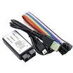
- 8-Channel USB Logic Analyzer - optional, useful for observing SDA/SCL traffic
- 830-Point Breadboard - for prototyping the breakout and wiring
- Dupont Jumper Wires - for SDA/SCL, power, and test connections
External
- ULN2803A high-current driver, TLP291-4 optocouplers
- MB2S bridge rectifier, XL1509-5.0 DC-DC converter, AMS1117-3.3 regulator
- 2-layer PCB (103x60 mm), SMD passives, terminal blocks
- 3D-printed DIN-rail enclosure (STL files in the original project)
Note: The MCP23017 has three address pins, allowing up to 8 expanders on one I2C bus. That is 128 extra I/O pins from two microcontroller pins.
Step-by-Step Guide
Step 1 - Why an I/O Expander
Goal: Understand the problem this solves.
What to do: Many automation projects run out of pins quickly: relays, sensors, indicators, and buttons add up. The MCP23017 adds 16 GPIO (two 8-bit ports, GPA and GPB) on the I2C bus, with per-pin direction, pull-ups, and interrupt support.
Your microcontroller can keep its own pins for timing-critical work and delegate the rest to the expander.
Expected result: A clear picture of where the expander fits in your designs.
Step 2 - Design the Industrial Version (Schematic)
Goal: See what separates a breakout from a cabinet-grade module.
What to do: The industrial design surrounds the MCP23017 with protection and drive circuitry: a bridge rectifier on the power entry (survives reversed wiring), a DC-DC converter accepting 5V or 24V cabinet power, TLP291-4 optocouplers isolating every input, and a ULN2803A Darlington array sinking real current on every output. DIP switches set the I2C address.

Expected result: You know what each supporting IC contributes.
Step 3 - Lay Out the PCB Like a PLC
Goal: Route a board an electrician would recognize.
What to do: The 103x60 mm 2-layer layout follows industrial conventions: power entry top-left, outputs along the top edge, inputs along the bottom, I2C connectors bottom-right, and a status LED for all 16 channels. Export Gerbers and send them to any board house.


Expected result: Fab-ready Gerbers (or use the author's shared design files).
Step 4 - Assemble: Paste, Place, Reflow, Inspect
Goal: Populate the SMD board cleanly.
What to do: Apply solder paste through the stencil, place the SMD parts with tweezers, reflow on a hot plate (about 245 C peak), then hand-solder the through-hole terminal blocks. Finish with an isopropyl clean and a microscope pass for bridges.


Expected result: A clean, bridge-free assembled board.
Step 5 - Test It from an Arduino
Goal: Drive all 16 channels over I2C.
What to do: Wire the board's I2C port to an Uno (SDA to A4, SCL to A5, plus GND). The same code also drives the ShillehTek pre-soldered breakout, so you can follow along without building the industrial board.
Install the Adafruit MCP23017 library and cycle the outputs:
Code:
#include <Wire.h>
#include "Adafruit_MCP23017.h"

Adafruit_MCP23017 expander;

void setup() {
  expander.begin(0);               // address offset 0 -> I2C 0x20
  for (int i = 8; i < 16; i++) {   // GPB0–GPB7 as outputs
    expander.pinMode(i, OUTPUT);
  }
}

void loop() {
  for (int i = 8; i < 16; i++) {   // chase the output LEDs
    expander.digitalWrite(i, HIGH);
    delay(150);
    expander.digitalWrite(i, LOW);
  }
}
A second test sketch mirrors the 8 inputs onto the 8 outputs. Flip any input and its output LED follows, proving every channel end to end.


Expected result: All 16 channels verified over two wires.
Step 6 - Mount It on the DIN Rail
Goal: Finish like a real automation product.
What to do: Place the board into the 3D-printed DIN-rail enclosure and clip it into the cabinet next to your PSU and PLC gear. Terminal blocks land the field wiring, and the I2C cable runs back to your controller.


Expected result: A cabinet-ready 16-channel I/O module.
Conclusion
The MCP23017 turns two I2C wires into 16 protected and indicated industrial-grade I/O channels. This build walks from Arduino Uno breakout-board testing to a reflowed, DIN-rail-mounted module suitable for a control cabinet.
Want the exact parts used in this build? Grab them from ShillehTek.com. If you want help customizing this project or building something for your product, check out our IoT consulting services.
Photo credit: images referenced from the original project by DIY GUY Chris on Hackster.io.






.png?v=25000753014097803521791168436)

.png?v=68677308723310773341791168436)


