

Project Overview
ESP32 + AMG8833 thermal camera: This project uses an ESP32 with an AMG8833 8x8 IR thermal sensor to display a live, interpolated colour heat map on a 2.8 inch ILI9341 TFT (plus a quick OLED character-map version).
The AMG8833 sees heat, not light: 64 thermopiles in an 8x8 grid, each reporting a temperature about ten times a second, out to about seven metres for a person. Sixty-four pixels sounds limited until you see what a little maths can do. This guide builds the camera twice. First the two-minute version with an OLED showing the grid as characters, enough to watch a hand warm the room. Then the full version: an ESP32 driving a 2.8 inch colour TFT with bilinear interpolation stretching the 8x8 frame to a smooth 64x64 image, an iron-style colour palette, auto-ranging, and a crosshair temperature readout.
- Time: ~1 hour
- Skill level: Beginner to Intermediate
- What you will build: A handheld thermal viewer with a 192x192-pixel interpolated heat map, colour scale, min/max labels and a centre-spot temperature, plus a minimal OLED version.

Parts List
From ShillehTek
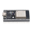
- ESP32 Dev Board (38-pin, CP2102, USB-C) - microcontroller that reads the sensor and drives the displays.
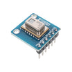
- AMG8833 8x8 IR Thermal Camera Sensor (pre-soldered) - thermal sensor that outputs 64 temperature readings over I2C.
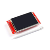
- ILI9341 2.8 inch SPI TFT (240x320) - fast colour display for the interpolated heat map.
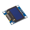
- 0.96 inch I2C OLED (SSD1306) - used for the quick character-map version.
- 830-Point Breadboard - for fast prototyping and clean wiring.
- Dupont Jumper Wires - to connect I2C and SPI signals.
External
- A USB power bank - if you want to walk around with it
Note: the AMG8833 measures 0 to 80 C with about ±2.5 C accuracy over a 60° field of view. It's superb for "where is the heat?" and good for relative comparisons, but it's not a calibrated thermometer. Like every thermal sensor it reads shiny metal badly because polished surfaces reflect the room instead of emitting their own temperature.
Step-by-Step Guide
Step 1 - Wire the sensor (I2C)
Goal: Connect the AMG8833 and OLED to the ESP32 over I2C.
What to do: Wire the AMG8833 as VIN to 3V3, GND to GND, SDA to GPIO21, and SCL to GPIO22.
Wire the OLED as VCC to 3V3, GND to GND, SDA to GPIO21, and SCL to GPIO22. Both devices share the same I2C bus. The OLED is typically at 0x3C. The AMG8833 is typically at 0x69 (or 0x68 on boards with the address pad bridged).
Install Adafruit AMG88xx and U8g2 from the Arduino Library Manager.

Expected result: Two I2C devices on one bus, ready for the first test sketch.
Step 2 - The two-minute version: OLED character heat map
Goal: Prove the sensor is working by drawing an 8x8 thermal grid as characters on the OLED.
What to do: Upload the sketch below, then wave your hand a hand-width in front of the sensor.
Code:
#include <Wire.h>
#include <U8x8lib.h>
#include <Adafruit_AMG88xx.h>

U8X8_SSD1306_128X64_NONAME_HW_I2C oled(U8X8_PIN_NONE);
Adafruit_AMG88xx amg;
float px[64];
const char SHADE[] = ".:-=+*#@";                 // 8 bands, coolest to hottest

void setup() {
  Wire.begin(21, 22);
  oled.begin();
  oled.setFont(u8x8_font_chroma48medium8_r);
  amg.begin();                                   // try amg.begin(0x68) if nothing shows
}

void loop() {
  amg.readPixels(px);                            // 64 temperatures in deg C
  for (int i = 0; i < 64; i++) {
    int level = constrain((int)((px[i] - 20.0) / (35.0 - 20.0) * 8), 0, 7);   // 20..35 C -> 8 bands
    char s[2] = { SHADE[level], 0 };
    oled.drawString((i % 8) * 2, i / 8, s);      // every other column keeps the grid square
  }
  delay(100);
}
Expected result: A grid of dots that turns into a cluster of # and @ where your hand is, following it around the frame. If the whole grid is @ or ., the room is outside 20 to 35 C, so change those two numbers.
Step 3 - Wire the colour TFT (SPI)
Goal: Connect the ILI9341 colour TFT on the fast SPI bus for real-time redraw.
What to do: Remove the OLED (or leave it; it is on I2C and will not conflict). Wire the ILI9341 to the ESP32 as VCC to 3V3, GND to GND, CS to GPIO5, RESET to GPIO16, DC to GPIO4, SDI (MOSI) to GPIO23, SCK to GPIO18, and LED to 3V3. Leave SDO and the touch pins unconnected.
These are the ESP32's hardware SPI pins, which matters because the display needs 64 rows redrawn about ten times a second. Install Adafruit ILI9341 and Adafruit GFX.
Expected result: The display backlight comes on, white and empty.
Step 4 - Build the interpolated thermal camera on the TFT
Goal: Read the 8x8 thermal frame, interpolate it to 64x64, and render a colour heat map with auto-ranging and a centre temperature readout.
What to do: Upload the sketch below and point the sensor at yourself from about a metre away.
Code:
#include <Wire.h>
#include <SPI.h>
#include <Adafruit_GFX.h>
#include <Adafruit_ILI9341.h>
#include <Adafruit_AMG88xx.h>

const int TFT_CS = 5, TFT_DC = 4, TFT_RST = 16;   // SCK 18, MOSI 23 = VSPI hardware pins
const int OUT = 64, CELL = 3;                     // 8x8 -> 64x64 cells, 3 px each = 192x192 image
const int X0 = 24, Y0 = 16;
const bool MIRROR = true;                         // true = selfie view, false = look-through view

Adafruit_ILI9341 tft(TFT_CS, TFT_DC, TFT_RST);
Adafruit_AMG88xx amg;
float px[64];
uint16_t band[OUT * CELL * CELL];                 // one row of cells: 192 x 3 pixels

float sampleAt(float gx, float gy) {              // bilinear interpolation between sensor points
  int x0 = (int)gx, y0 = (int)gy;
  int x1 = min(x0 + 1, 7), y1 = min(y0 + 1, 7);
  float fx = gx - x0, fy = gy - y0;
  float top = px[y0 * 8 + x0] * (1 - fx) + px[y0 * 8 + x1] * fx;
  float bot = px[y1 * 8 + x0] * (1 - fx) + px[y1 * 8 + x1] * fx;
  return top * (1 - fy) + bot * fy;
}

uint16_t iron(float t) {                          // 0..1 -> black, blue, purple, red, orange, yellow, white
  static const uint8_t stops[7][3] = {{0,0,0},{0,0,140},{150,0,170},{230,30,30},{255,140,0},{255,230,40},{255,255,255}};
  t = constrain(t, 0.0f, 1.0f);
  float p = t * 6; int i = min((int)p, 5); float f = p - i;
  uint8_t r = stops[i][0] + (stops[i + 1][0] - stops[i][0]) * f;
  uint8_t g = stops[i][1] + (stops[i + 1][1] - stops[i][1]) * f;
  uint8_t b = stops[i][2] + (stops[i + 1][2] - stops[i][2]) * f;
  return tft.color565(r, g, b);
}

void setup() {
  Wire.begin(21, 22);
  tft.begin(40000000);                            // 40 MHz SPI
  tft.setRotation(0);
  tft.fillScreen(ILI9341_BLACK);
  if (!amg.begin()) {                             // amg.begin(0x68) for the alternate address
    tft.setTextColor(ILI9341_RED); tft.setCursor(10, 10); tft.print("AMG8833 not found"); while (1);
  }
  for (int i = 0; i < OUT * CELL; i++)            // colour scale under the image
    tft.drawFastVLine(X0 + i, Y0 + OUT * CELL + 8, 10, iron(i / (OUT * CELL - 1.0)));
}

void loop() {
  amg.readPixels(px);
  float lo = 1000, hi = -1000;
  for (int i = 0; i < 64; i++) { lo = min(lo, px[i]); hi = max(hi, px[i]); }
  if (hi - lo < 4) hi = lo + 4;                   // don't stretch sensor noise across the palette

  for (int cy = 0; cy < OUT; cy++) {
    for (int cx = 0; cx < OUT; cx++) {
      float gx = cx * 7.0 / (OUT - 1), gy = cy * 7.0 / (OUT - 1);
      if (MIRROR) gx = 7.0 - gx;
      uint16_t c = iron((sampleAt(gx, gy) - lo) / (hi - lo));
      for (int dy = 0; dy < CELL; dy++)
        for (int dx = 0; dx < CELL; dx++) band[dy * OUT * CELL + cx * CELL + dx] = c;
    }
    tft.drawRGBBitmap(X0, Y0 + cy * CELL, band, OUT * CELL, CELL);   // one fast SPI burst per row
  }
  tft.drawCircle(X0 + OUT * CELL / 2, Y0 + OUT * CELL / 2, 5, ILI9341_WHITE);   // centre crosshair

  float centre = (px[27] + px[28] + px[35] + px[36]) / 4;           // the 4 middle pixels
  int ty = Y0 + OUT * CELL + 24;
  tft.fillRect(0, ty, 240, 70, ILI9341_BLACK);
  tft.setTextColor(ILI9341_WHITE); tft.setTextSize(1);
  tft.setCursor(X0, ty); tft.print(lo, 1); tft.print(" C");
  tft.setCursor(X0 + 150, ty); tft.print(hi, 1); tft.print(" C");
  tft.setTextSize(3); tft.setCursor(X0 + 40, ty + 20); tft.print(centre, 1); tft.print(" C");
}
Expected result: A smooth heat map: your face and neck glowing yellow-white, your clothes red, and the wall behind you deep blue. The colour scale stretches automatically between the coldest and hottest pixel (labels underneath), and the big number is the temperature at the crosshair. If moving left moves you right on screen, set MIRROR to false.
Step 5 - Understand why 64 pixels look like more
Goal: Understand what the interpolation and auto-ranging are doing.
What to do: The sensor still only knows 64 temperatures. Interpolation does not add detail; it removes the blockiness. The sampleAt() function estimates the temperature between four neighbouring sensor points by weighting each by how close it is, so a warm patch becomes a smooth blob instead of a hard square.
Auto-ranging maps the coldest-to-hottest span of each frame onto the full palette, so a small temperature difference can fill the screen with contrast. Try a fixed range (lo = 20; hi = 40;) to compare scenes frame to frame, which is useful when you are looking for one hot spot rather than a pretty picture.
Expected result: You know when to trust the picture and when to trust the number.
Step 6 - Put it to work
Goal: Apply the thermal viewer to real tasks.
What to do: Hold it over a running circuit board to find the component that is working too hard. Sweep window frames and door edges on a cold day for draughts. Mount it on the ceiling as a privacy-friendly occupancy sensor and publish a people count over MQTT.
You can also add the TFT's touch controller to switch palettes and fixed or auto range, or log frames to the micro SD module for time-lapse heat studies.
Expected result: A thermal camera that earns its place in the toolbox.
Conclusion
Eight by eight is enough. A character map on an OLED proves the AMG8833 works in two minutes; an ESP32, a fast SPI display, and interpolation plus colour mapping turn the same 64 numbers into an image you can actually read. It will not replace a professional imager, but for finding heat in a board, a house, or a room, it is excellent value.
Want the exact parts used in this build? Grab them from ShillehTek.com. If you want help customizing this project or building something for your product, check out our IoT consulting services.
Credits: All photos and images in this tutorial are credited to berniebe on Hackster.io (MIT license). The original guide by berniebe served as the reference for this ShillehTek version.




.png?v=25000753014097803521791168436)

.png?v=68677308723310773341791168436)


