

Project Overview
Joystick-Controlled Pan-Tilt Servo Mount with Arduino: Use an Arduino Uno with an analog joystick module (KY-023 style) to drive a two-axis pan-tilt servo mount with smooth proportional speed and a click-to-recenter button.
The original project drove the two servos from a four-way switch joystick. This version uses the common analog thumbstick module, which gives you variable speed and diagonal movement from the same two servo outputs. It is the control scheme behind camera gimbals, turret toys, and remote inspection rigs.
- Time: ~45 minutes
- Skill level: Beginner
- What you will build: A two-axis servo mount steered by a joystick, with a dead zone, proportional speed, travel limits, and a recenter button.

Parts List
From ShillehTek
- Arduino Uno R3 Super Starter Kit - Uno plus an SG90 servo and jumpers
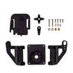
- Pan-Tilt Servo Bracket Kit - the mechanical mount for pan and tilt
- MG995 Metal Gear Servo - for a heavier payload such as a camera
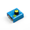
- Servo Tester - center the servos before assembly
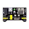
- MB102 Breadboard Power Supply - a clean 5 V rail for the servos
- 400-Point Breadboard - for power distribution and wiring
- Dupont Jumper Wires - to connect joystick, servos, and power rails
External
- An analog joystick module (KY-023 style: VRx, VRy, SW)
Note: A joystick is two potentiometers at right angles plus a button. At rest each axis reads about 512, but never exactly, and it wobbles. The dead zone in the code ignores small deviations so the mount does not creep when your hand is off the stick.
Step-by-Step Guide
Step 1 - Center and Assemble the Servos
Goal: Full travel in both directions.
What to do: Plug each servo into the servo tester and set it to the center position, then attach the horns and build the bracket so the platform is level and facing forward at 90°. Skipping this is how people end up with a mount that can only look left.
Expected result: A pan-tilt mount that is square at its midpoint.
Step 2 - Wire Joystick and Servos
Goal: Two analog inputs, one button, two PWM outputs.
What to do: Joystick: VCC to 5V, GND to GND, VRx to A0, VRy to A1, SW to D2. Servos: pan signal to D9, tilt signal to D10. Power the servos from the MB102 5 V rail (or the Arduino 5V pin for a single SG90 pair), with all grounds tied together.

Expected result: Everything shares a ground and the servos have real current available.
Step 3 - Upload the Sketch
Goal: Read the joystick, apply a dead zone, and move pan and tilt with proportional speed.
What to do: Paste the sketch below into the Arduino IDE and upload it to your Arduino Uno.
Code:
#include <Servo.h>

Servo pan, tilt;
const int JOY_X = A0, JOY_Y = A1, JOY_SW = 2;
const int CENTER = 512, DEAD = 60;      // ignore stick wobble near the middle
const int MAX_STEP = 3;                 // degrees per update at full deflection
int panPos = 90, tiltPos = 90;

int stepFor(int raw) {                  // returns -MAX_STEP..+MAX_STEP, 0 in the dead zone
  int d = raw - CENTER;
  if (abs(d) < DEAD) return 0;
  return map(d, -512, 511, -MAX_STEP, MAX_STEP);
}

void setup() {
  pan.attach(9); tilt.attach(10);
  pinMode(JOY_SW, INPUT_PULLUP);
  pan.write(panPos); tilt.write(tiltPos);
}

void loop() {
  panPos  += stepFor(analogRead(JOY_X));           // push further = move faster
  tiltPos += stepFor(analogRead(JOY_Y));
  panPos  = constrain(panPos, 0, 180);
  tiltPos = constrain(tiltPos, 20, 160);           // keep the bracket off its mechanical stops

  if (digitalRead(JOY_SW) == LOW) { panPos = 90; tiltPos = 90; }   // click = recenter

  pan.write(panPos);
  tilt.write(tiltPos);
  delay(15);                                       // ~66 updates per second
}
Expected result: Upload and nudge the stick. A light push creeps; a full push sweeps. Click the stick to snap back to center. Control should feel smooth and not drift at rest.
If an axis moves the wrong way, swap the sign in that line (or swap A0/A1 if pan and tilt are crossed).
Step 4 - Tune the Feel
Goal: Make it pleasant to drive.
What to do: Raise DEAD if it creeps, lower it if the center feels mushy. Lower MAX_STEP for fine camera framing or raise it for a snappy turret. For an "absolute" mode where stick position equals mount position (like the original switch-based build's direct control), replace the increment with panPos = map(analogRead(JOY_X), 0, 1023, 0, 180).
Expected result: Control tuned for your mount and your thumb.
Step 5 - Put Something on It
Goal: Turn the mount into a useful rig.
What to do: Mount a phone or small camera and you have a manual gimbal for time-lapses. Add a laser pointer for a cat toy. Swap the joystick for two pots at the end of a long cable, or for an HC-05 Bluetooth module reading the same two axes from a phone app, and it becomes a remote inspection head.
Expected result: A pan-tilt platform that does a job you care about.
Conclusion
Read two axes, apply a dead zone, scale to a step size, clamp to limits, and you have a simple recipe for smooth manual control of servo motion. With an Arduino Uno, an analog joystick module, and two servos, you now have a proportional pan-tilt mount with travel limits and a click-to-recenter control.
Want the exact parts used in this build? Grab them from ShillehTek.com. If you want help customizing this project or building something for your product, check out our IoT consulting services.
Credits: All photos and images in this tutorial are credited to ejshea on Hackster.io. The original guide by ejshea served as the reference for this ShillehTek version.






.png?v=25000753014097803521791168436)

.png?v=68677308723310773341791168436)


