

Project Overview
Arduino + 28BYJ-48 stepper motor with the ULN2003 driver: In this project, you will wire a 28BYJ-48 5V geared stepper motor to an Arduino through a ULN2003 driver module and run a sketch that turns the shaft one full revolution in each direction.
Stepper motors move in precise, repeatable increments without feedback sensors, which is why they are used in 3D printers, CNC machines, and robotics. The 28BYJ-48 is an easy way to learn because it is low cost, runs on 5V, and plugs directly into the ULN2003 module via a keyed connector.
- Time: 45 minutes
- Skill level: Beginner
- What you will build: Precise, repeatable motor motion with one clean revolution clockwise, then counter-clockwise.

Parts List
From ShillehTek
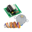
- 28BYJ-48 Stepper Motor + ULN2003 Driver Kit - includes both parts (motor also sold separately)
- Arduino Nano V3 - or any Arduino UNO-compatible board
- 120pcs 20cm Dupont Jumper Wires - plus an optional breadboard
External
- USB cable for the Arduino
Note: For continuous or high-load use, power the ULN2003 VCC from an external 5V supply rather than the Arduino 5V pin. Steppers hold current even when stationary.
Step-by-Step Guide
Step 1 - How a Stepper Motor Works
Goal: Understand steps, coils, and drive modes.
What to do: A stepper divides a rotation into equal steps by energizing coils in sequence. The magnetized rotor follows the rotating magnetic field one increment at a time, which gives precise position control without an encoder.
Four common drive modes:
- Wave stepping - one coil at a time (low power, low torque)
- Full-step (two-phase-on) - two coils at a time (higher torque)
- Half-step - alternates one and two coils (double resolution, slightly less torque)
- Microstepping - current control for smooth motion (requires a more advanced driver)

Expected result: You can explain why steppers position precisely without sensors.
Step 2 - Meet the 28BYJ-48
Goal: Understand the motor specs and wiring.
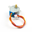
What to do: Key specs include 5V rated, 4 phases, and a stride angle of 5.625°/64 with a 1/64 gear reduction. The internal rotor spins 64 times for one output-shaft turn, increasing torque and resolution (2048 full steps per output revolution).
The five wires are blue, pink, yellow, and orange for the four coil ends, plus a red common wire tied to the driver supply rail via the keyed connector.

Expected result: You understand why 2048 steps equals one output-shaft revolution.
Step 3 - Meet the ULN2003 Driver
Goal: Understand what the driver does and what its pins mean.
What to do: Arduino pins cannot sink the current required by stepper coils, so the ULN2003 Darlington transistor array switches the coil current for you. The module exposes IN1 to IN4 (logic inputs from the Arduino), a keyed motor connector (OUT1 to OUT4 internally), plus VCC and GND.
Onboard LEDs blink as each coil is energized, which helps you confirm the stepping sequence.

Expected result: You know the ULN2003 is used to switch coil current and protect the Arduino I/O pins.
Step 4 - Wire Everything
Goal: Connect motor to driver and driver to Arduino.
What to do: Plug the 28BYJ-48 motor connector into the ULN2003 module. It is keyed, so it only fits one way. Then wire the ULN2003 to the Arduino as shown:
ULN2003 IN1 -> Arduino D7
ULN2003 IN2 -> Arduino D6
ULN2003 IN3 -> Arduino D5
ULN2003 IN4 -> Arduino D4
ULN2003 GND -> Arduino GND
ULN2003 VCC -> Arduino 5V
Expected result: The motor is plugged into the ULN2003, and IN1 to IN4 are wired to Arduino D7 to D4.
Step 5 - Upload the Rotation Sketch
Goal: Rotate one revolution each direction repeatedly.
What to do: Use the built-in Arduino Stepper library. Pay attention to the constructor pin order (IN1, IN3, IN2, IN4 pattern) which matches how the coils are paired.
Code:
#include <Stepper.h>

// Driver input pins
#define OUTPUT1 7 // IN1 (Blue coil wire)
#define OUTPUT2 6 // IN2 (Pink coil wire)
#define OUTPUT3 5 // IN3 (Yellow coil wire)
#define OUTPUT4 4 // IN4 (Orange coil wire)

// 28BYJ-48: 2048 steps per output revolution in full-step mode
const int stepsPerRotation = 2048;

// Pin sequence OUTPUT1, OUTPUT3, OUTPUT2, OUTPUT4 pairs the coils correctly
Stepper myStepper(stepsPerRotation, OUTPUT1, OUTPUT3, OUTPUT2, OUTPUT4);

void setup() {
  myStepper.setSpeed(15); // RPM
}

void loop() {
  // One full rotation clockwise
  myStepper.step(stepsPerRotation);
  delay(1000);
  // One full rotation the other way
  myStepper.step(-stepsPerRotation);
  delay(1000);
}
Expected result: The shaft turns exactly one revolution, pauses, then returns one revolution in the opposite direction. Change the sign to change direction, and change the step count to change angle (for example, 512 steps is a quarter turn).
Conclusion
You learned stepper drive concepts (wave, full, half, and microstepping), why the 28BYJ-48 gearbox produces 2048 steps per output-shaft revolution, and how to drive it using an Arduino with a ULN2003 module and the Stepper library.
Photo and reference credit: Instructables (original guide and code by Rachana Jain), used as a reference for this ShillehTek version.
Want the exact parts used in this build? Grab them from ShillehTek.com. If you want help customizing this project or building something for your product, check out our IoT consulting services.





.png?v=25000753014097803521791168436)

.png?v=68677308723310773341791168436)


