

Project Overview
Arduino + S8050 NPN transistor switch: In this project, you will use an Arduino Uno pin to safely switch higher-current loads using an S8050 NPN transistor, including a 12 V LED strip and a DC motor, with the correct base resistor and a required flyback diode.
An Arduino pin can supply about 20 mA. A motor may want 200 mA, an LED strip 500 mA, and a relay coil 70 mA at a voltage the pin does not even have. This guide uses the S8050 NPN from a common transistor kit to switch a 12 V LED strip and PWM a gear motor from a 5 V pin, shows how to pick the base resistor with one line of arithmetic, explains why the diode across a motor is not optional, and finishes with a PNP high-side trick and a Darlington pair for bigger loads.
- Time: ~40 minutes
- Skill level: Beginner
- What you will build: Two working low-side switches (a blinking 12 V strip and a speed-ramping motor), a base-resistor rule, and wiring concepts for PNP and Darlington versions.

Parts List
From ShillehTek
- Arduino Uno R3 Super Starter Kit - the controller used to drive the transistor bases.
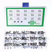
- 300-Piece Transistor Kit (S8050, S8550, S9012, S9013, S9014) - provides the S8050 NPN (and S8550 PNP for the high-side example).
- Diode Kit - includes 1N4007 flyback diodes for motors, relays, and other coils.
- Resistor Kit - for base resistors (470 ohm, 1k ohm, 10k ohm) and pull-downs.
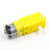
- TT Gear Motor - example inductive load to switch with PWM.
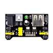
- MB102 Breadboard Power Supply - provides a separate 5 V rail for the motor (not from the Arduino 5 V pin).
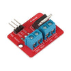
- IRF520 MOSFET Module - a next step option when you need more current.
- 830-Point Breadboard - for building the circuits.
- Dupont Jumper Wires - for connections between the Arduino, transistor, and load.
External
- A short piece of 12 V LED strip and a 12 V supply (optional; a 5 V LED cluster from the kit works too).
Note: Pinouts differ between transistor families. The S8050/S8550/S9013/S9014 in this kit are TO-92 parts whose legs, with the flat face toward you and legs down, are Emitter-Base-Collector left to right. A BC547 or 2N2222 from another kit is often C-B-E. Check the datasheet before you assume.
Step-by-Step Guide
Step 1 - Meet the S8050
Goal: Understand the three numbers that matter for switching.
What to do: The S8050 is an NPN rated for 700 mA collector current and 25 V, with a current gain (hFE) of roughly 100 to 300. Used as a switch it has two states: off (no base current, collector open) and saturated (enough base current that the collector pulls to about 0.2 V above the emitter).
Everything in this guide is about making sure you are firmly in one of those two states, never in between, where it turns into a heater.
Expected result: You think of it as a pin-controlled switch to ground, not an amplifier.
Step 2 - Pick the Base Resistor
Goal: Choose a base resistor with one line of arithmetic.
What to do: For a hard switch, aim for a base current of about a tenth of the load current: Ib = Ic / 10. The base sits at about 0.7 V, so Rb = (Vpin - 0.7) / Ib.
Example (100 mA LED strip): Ib = 10 mA, so Rb = 4.3 / 0.01 = 430 ohm, then use 470 ohm. Example (200 mA motor): Ib = 20 mA, so Rb = 215 ohm, then use 220 ohm, which is right at the Arduino pin's limit.
For loads above about 150 mA, move to the Darlington in Step 6 (where ~1 mA base current can do the job) or use a MOSFET. Add a 10k ohm resistor from base to ground so the transistor stays off while the Arduino boots and the pin floats.
Expected result: A practical rule of thumb: 470 ohm for small loads, Darlington or MOSFET for bigger ones.
Step 3 - Wire Two Low-Side Switches
Goal: Control a 12 V LED strip and a motor, each on its own transistor.
What to do: Wire Switch 1 (LED strip): D5 to 470 ohm to base; emitter to GND; collector to LED strip negative; LED strip positive to 12 V supply positive; supply negative to Arduino GND. Shared ground is essential.
Wire Switch 2 (motor): D6 to 470 ohm to base; emitter to GND; collector to motor wire 1; motor wire 2 to the MB102 5 V rail; MB102 GND to Arduino GND. Put a 1N4007 across the motor with the band toward the 5 V side. Add a 10k ohm from each base to GND to keep the transistors off at boot.
Expected result: Two loads at two different voltages, both controlled by 5 V pins, both sharing ground with the Arduino.
Step 4 - Upload the Sketch
Goal: Blink the strip and ramp the motor speed with PWM.
Code:
const int STRIP = 5;      // S8050 base via 470 ohm: 12 V LED strip, on/off
const int MOTOR = 6;      // S8050 base via 470 ohm: 5 V gear motor, PWM

void setup() {
  pinMode(STRIP, OUTPUT); pinMode(MOTOR, OUTPUT);
  Serial.begin(9600);
}

void loop() {
  digitalWrite(STRIP, HIGH); Serial.println("strip ON");   // 5 V pin switches a 12 V load
  for (int s = 0; s <= 255; s += 5) { analogWrite(MOTOR, s); delay(30); }   // ramp up
  delay(500);
  for (int s = 255; s >= 0; s -= 5) { analogWrite(MOTOR, s); delay(30); }   // ramp down
  digitalWrite(STRIP, LOW);  Serial.println("strip OFF");
  delay(1000);
}
What to do: Upload the sketch to your Arduino.
Expected result: The strip lights while the motor ramps from stopped to full speed and back down, then the strip turns off for a second. The transistors should stay cool. If one is warm, it is not saturating; reduce the base resistor value or move to the Darlington approach.
Step 5 - Understand Why the Diode Matters
Goal: Avoid damaging the transistor when switching an inductive load.
What to do: With power off, remove the diode and run the sketch. It may still work for a while, but every time the transistor switches off, the motor's inductance produces a spike far above 25 V. The S8050 absorbs part of that energy repeatedly until it fails, often shorted.
The 1N4007 gives the current a safe loop back through the motor instead. Reinstall the diode. Use the same rule for relays, solenoids, and other coils.
Expected result: You treat the flyback diode as a required part for motors and coils, not an optional extra.
Step 6 - PNP High-Side Switching and a Darlington Pair
Goal: Learn two more useful transistor switch variations from the same kit.
What to do: High-side switching (load between transistor and ground, useful when the load negative must be grounded): use the S8550 PNP with its emitter on +12 V and the load on its collector. A 5 V pin cannot directly turn a 12 V PNP off, so drive its base through a 1k ohm resistor from the collector of an S8050 that your pin controls (pin HIGH to NPN on to PNP on).
Darlington pair (for roughly 300 to 700 mA with very little pin current): connect the collector of a first S8050 to the collector of a second; connect the emitter of the first to the base of the second; connect the second emitter to GND; drive the first base through 4.7k ohm. The gain multiplies (about 100 x 100), so about 1 mA of base current can switch around half an amp, but the tradeoff is about 1 V dropped across the pair.
Expected result: You can switch either side of a load and drive many small motors without a driver board, and you know when to step up to a MOSFET or motor driver.
Conclusion
With an Arduino Uno and an S8050 NPN transistor, you can switch loads that draw far more current (and even higher voltages) than a GPIO pin can supply. The key ideas are simple: size the base resistor using Ic / 10, wire emitter to ground with the load on the collector for low-side switching, and add a flyback diode across any coil or motor.
Want the exact parts used in this build? Grab them from ShillehTek.com. If you want help customizing this project or building something for your product, check out our IoT consulting services.
Credits: All photos and images in this tutorial are credited to curiores on Hackster.io (CC BY 4.0 license). The original guide by curiores served as the reference for this ShillehTek version.






.png?v=25000753014097803521791168436)

.png?v=68677308723310773341791168436)


