

Project Overview
MPU6050 Tilt Game and Digital Level on an OLED: Use an Arduino Nano with an MPU6050 IMU and an SSD1306 OLED to build a tilt-controlled game and a digital spirit level with stable pitch and roll angles from a complementary filter.
Tilt the board and a ball rolls across the OLED; collect the targets before the clock runs out. Hold a button and the same hardware becomes a bubble level that shows pitch and roll to a tenth of a degree.
This project teaches how to turn raw accelerometer and gyro readings into stable angles with a complementary filter, which is a core technique used in balancing robots, gimbals, and motion controllers.
- Time: ~1 hour
- Skill level: Intermediate
- What you will build: A tilt-controlled arcade game with a 60-second timer and score, plus a precision level mode using sensor fusion.

Parts List
From ShillehTek
- Arduino Nano V3.0 Pre-Soldered - the microcontroller that reads the IMU and drives the OLED
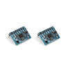
- MPU6050 Pre-Soldered IMU (2-Pack) - accelerometer and gyroscope used for pitch/roll and tilt control
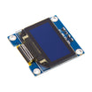
- SSD1306 0.96" I2C OLED - displays the game and bubble level UI
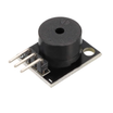
- KY-006 Passive Buzzer - sound feedback when you hit a target or time expires
- Tactile Button Kit - mode button for game versus level
- 400-Point Breadboard - quick prototyping and wiring
- Dupont Jumper Wires - connections between the Nano and modules
External
- A 9 V battery or USB power bank to make it handheld
Note: The accelerometer gives a true angle but is noisy and jumps when you move; the gyro is smooth but drifts over time. A complementary filter blends them (98% gyro for smoothness, 2% accelerometer to pull the drift back) in a single line of code.
Step-by-Step Guide
Step 1 - Wire IMU, Display, Button, Buzzer
Goal: Put everything on one I2C bus and connect the inputs/outputs.
What to do: Wire the MPU6050 and OLED to the Arduino Nano I2C pins: SDA to A4, SCL to A5 (they have different addresses: 0x68 and 0x3C). Connect MPU6050 VCC to 5V (the module has a regulator), OLED VCC to 5V, and both GND pins to GND. Wire the button from D7 to GND. Wire the buzzer to D8.

Expected result: Two I2C devices (MPU6050 and OLED) and two extra parts (button and buzzer) wired to the Nano.
Step 2 - Get Stable Angles
Goal: Compute pitch and roll that stay smooth and do not drift.
What to do: Read raw accelerometer and gyro values from the MPU6050 registers (no IMU library required), convert the accelerometer to an angle using atan2, integrate the gyro rate over time, and blend them using a complementary filter. Print the results and rock the board: the numbers should move smoothly and settle when you stop moving.
Expected result: Pitch and roll in degrees that are smooth and drift-free.
Step 3 - Upload the Sketch
Goal: Run the game mode and level mode on the OLED.
What to do: Upload this sketch to your Arduino Nano. Then hold the board flat and tilt it gently toward the target square.
Code:
#include <Wire.h>
#include <Adafruit_GFX.h>
#include <Adafruit_SSD1306.h>

Adafruit_SSD1306 oled(128, 64, &Wire, -1);
const int MPU = 0x68, BTN = 7, BUZZ = 8;
float pitch = 0, roll = 0;
unsigned long lastUs = 0;

// ---- sensor fusion ----
void readIMU() {
  Wire.beginTransmission(MPU); Wire.write(0x3B); Wire.endTransmission(false);
  Wire.requestFrom(MPU, 14, true);
  int16_t ax = Wire.read() << 8 | Wire.read(), ay = Wire.read() << 8 | Wire.read(), az = Wire.read() << 8 | Wire.read();
  Wire.read(); Wire.read();                                        // skip temperature
  int16_t gx = Wire.read() << 8 | Wire.read(), gy = Wire.read() << 8 | Wire.read(); Wire.read(); Wire.read();

  float accPitch = atan2(ay, az) * 57.3;                           // degrees from gravity
  float accRoll  = atan2(-ax, az) * 57.3;
  unsigned long now = micros(); float dt = (now - lastUs) / 1e6; lastUs = now;
  pitch = 0.98 * (pitch + gx / 131.0 * dt) + 0.02 * accPitch;      // complementary filter
  roll  = 0.98 * (roll  + gy / 131.0 * dt) + 0.02 * accRoll;
}

// ---- game state ----
float bx = 64, by = 32; int tx, ty, score; unsigned long gameEnd;
void newTarget() { tx = random(8, 120); ty = random(8, 56); }

void setup() {
  Wire.begin();
  Wire.beginTransmission(MPU); Wire.write(0x6B); Wire.write(0); Wire.endTransmission();   // wake up
  oled.begin(SSD1306_SWITCHCAPVCC, 0x3C); oled.setTextColor(SSD1306_WHITE);
  pinMode(BTN, INPUT_PULLUP);
  randomSeed(analogRead(A0));
  lastUs = micros(); newTarget(); gameEnd = millis() + 60000;
}

void loop() {
  readIMU();
  oled.clearDisplay();

  if (digitalRead(BTN) == LOW) {                                   // ---- LEVEL MODE ----
    int cx = 64 + constrain(roll, -30, 30) * 2, cy = 32 + constrain(pitch, -30, 30) * 1;
    oled.drawCircle(64, 32, 20, SSD1306_WHITE); oled.drawCircle(64, 32, 3, SSD1306_WHITE);
    oled.fillCircle(cx, cy, 4, SSD1306_WHITE);                     // the bubble
    oled.setTextSize(1);
    oled.setCursor(0, 0);  oled.print("P "); oled.print(pitch, 1);
    oled.setCursor(0, 56); oled.print("R "); oled.print(roll, 1);
    if (abs(pitch) < 0.5 && abs(roll) < 0.5) { oled.setCursor(92, 0); oled.print("LEVEL"); }
  } else {                                                         // ---- GAME MODE ----
    bx = constrain(bx + roll * 0.08, 2, 125);                      // tilt = velocity
    by = constrain(by + pitch * 0.08, 2, 61);
    if (abs(bx - tx) < 5 && abs(by - ty) < 5) { score++; tone(BUZZ, 1200, 60); newTarget(); }
    long left = (gameEnd - millis()) / 1000;
    if (left <= 0) {                                               // time's up
      oled.setTextSize(2); oled.setCursor(16, 20); oled.print("SCORE "); oled.print(score);
      oled.display(); tone(BUZZ, 300, 500); delay(3000);
      score = 0; bx = 64; by = 32; gameEnd = millis() + 60000; return;
    }
    oled.drawRect(tx - 3, ty - 3, 7, 7, SSD1306_WHITE);            // target
    oled.fillCircle((int)bx, (int)by, 3, SSD1306_WHITE);           // ball
    oled.setTextSize(1); oled.setCursor(0, 0); oled.print(score);
    oled.setCursor(110, 0); oled.print(left);
  }
  oled.display();
}
Expected result: In game mode, the ball moves with tilt, chirps and scores when it reaches a target, and the timer counts down from 60 seconds. While holding the button, the display switches to a bubble level with live pitch and roll, and it shows "LEVEL" when both angles are within 0.5 degrees.
Step 4 - Calibrate for a True Level
Goal: Make zero mean flat for your specific build.
What to do: Place the finished device on a surface you trust, note the pitch and roll it reports, and subtract those offsets in the sketch. The original build also suggests storing offsets in EEPROM with a long-press calibration.
Expected result: The bubble is centered when the surface really is level, matching a physical bubble level to a fraction of a degree.
Step 5 - Make It Handheld and Push Further
Goal: Turn the breadboard build into a portable project and reuse the IMU code.
What to do: Put the circuit in a box with a battery to make it both a pocket toy and a workshop tool. Reuse the same angle code for bigger projects like a self-leveling servo platform, a tilt-steered robot, or a motion-controlled PC game over Serial.
Expected result: You can reuse the same complementary filter approach in future motion-based projects.
Conclusion
In this build, the Arduino Nano reads an MPU6050 and uses a complementary filter to create stable pitch and roll for a tilt game and a digital bubble level on an SSD1306 OLED. The same sensor fusion idea is used in many real motion-control systems, and now you have a working implementation you can extend.
Want the exact parts used in this build? Grab them from ShillehTek.com. If you want help customizing this project or building something for your product, check out our IoT consulting services.
Credits
All photos and images in this tutorial are credited to Mirko Pavleski on Hackster.io. The original guide by Mirko Pavleski served as the reference for this ShillehTek version. We thank him for his excellent work in the maker community.





.png?v=25000753014097803521791168436)

.png?v=68677308723310773341791168436)


