

Project Overview
Arduino Nano + MPU6050 self-balancing robot: In this build, an Arduino Nano reads an MPU6050 IMU to estimate tilt angle, then uses a PID loop to drive an L298N motor driver so a two-wheeled robot stays upright.
An MPU6050 measures how far the body is leaning, a complementary filter turns the noisy accelerometer and drifting gyro into one clean angle, and a PID loop drives the wheels under the robot fast enough that it never falls.
- Time: ~2 hours (plus tuning)
- Skill level: Intermediate-Advanced
- What you will build: A balancing robot with a 200 Hz control loop, gyro auto-calibration, fall detection, and a tuning procedure that converges.

Parts List
From ShillehTek
- Arduino Nano V3.0 Pre-Soldered - runs the 200 Hz control loop and PWM motor control
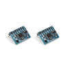
- MPU-6050 Accelerometer/Gyro (pre-soldered) - measures tilt using accelerometer + gyro over I2C
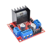
- L298N Motor Driver - drives both DC motors from the battery (the original used an L293D; same pins, less current)
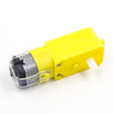
- TT Gear Motor 1:48 ×2 - left and right drive motors
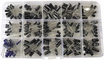
- Electrolytic Capacitor Kit - use a 220 µF cap across the Nano 5V and GND to smooth supply dips
- 400-Point Breadboard - quick prototyping and wiring
- Dupont Jumper Wires - connections between Nano, MPU6050, and L298N
External
- Two wheels for TT motors, and a tall narrow chassis (two acrylic/plywood decks on standoffs, or a 3D print)
- A 7.4 V battery: two 18650 cells in a 2S holder, or 6×AA
Note: Geometry matters more than code. Mount the battery (the heaviest part) as high as possible. A tall robot falls slowly and is easier to balance; a squat one falls fast and is nearly impossible. Mount the MPU6050 rigidly, close to the wheel axle, with its board flat and one edge facing straight forward.
Step-by-Step Guide
Step 1 - Build the Chassis
Goal: A tall, stiff body on two wheels.
What to do: Bolt the two TT motors to the bottom deck, wheels on the outside, axles in line. Stack a second deck above for the Nano, breadboard, and driver, and put the battery on the top deck.
Anything that wobbles adds noise the loop has to fight, so tighten everything.
Expected result: The robot stands (held) with its centre of mass well above the axle.
Step 2 - Wire It
Goal: Sensor to Nano, Nano to driver, driver to motors.
What to do: Wire the MPU6050 to the Nano: VCC → 5V, GND → GND, SDA → A4, SCL → A5.
Wire the L298N to the Nano: ENA → D3, IN1 → D4, IN2 → D8, IN3 → D5, IN4 → D7, ENB → D6. Connect OUT1/OUT2 → left motor and OUT3/OUT4 → right motor.
Power wiring: +12V → battery +, GND → battery − and Nano GND. Leave the L298N 5 V jumper on and feed its 5V pin to the Nano 5V pin.
Add the 220 µF capacitor across the Nano 5V and GND. Remove the ENA/ENB jumpers so the PWM pins control speed.

Expected result: Everything is powered from one battery through the driver regulator.
Step 3 - Upload the Sketch
Goal: Read tilt angle, run a complementary filter, and drive the motors with PID at 200 Hz.
Code:
#include <Wire.h>
const int ENA = 3, IN1 = 4, IN2 = 8, IN3 = 5, IN4 = 7, ENB = 6;
const uint8_t MPU = 0x68;

// ---- tuning (see Step 5) ----
float Kp = 20.0, Ki = 150.0, Kd = 0.6;
float setpoint  = 0.0;          // degrees: the angle at which the robot is truly balanced
const int   MIN_PWM    = 40;    // motors don't turn below this
const float FALL_ANGLE = 35.0;  // give up beyond this

float angle = 0, integral = 0, lastErr = 0, gyroOffset = 0;
unsigned long lastUs;

void mpuWrite(uint8_t reg, uint8_t val) {
  Wire.beginTransmission(MPU); Wire.write(reg); Wire.write(val); Wire.endTransmission();
}
void mpuRead(int16_t& ax, int16_t& az, int16_t& gy) {
  Wire.beginTransmission(MPU); Wire.write(0x3B); Wire.endTransmission(false);
  Wire.requestFrom(MPU, (uint8_t)14);
  ax = Wire.read() << 8 | Wire.read();  Wire.read(); Wire.read();   // ax, (ay skipped)
  az = Wire.read() << 8 | Wire.read();
  Wire.read(); Wire.read();                                        // temperature
  Wire.read(); Wire.read();                                        // gx
  gy = Wire.read() << 8 | Wire.read();                              // gyro around the axle
  Wire.read(); Wire.read();                                        // gz
}

void drive(int pwm) {                       // -215..215, positive = forward
  bool fwd = pwm > 0; pwm = abs(pwm);
  if (pwm > 0) pwm = constrain(pwm + MIN_PWM, 0, 255);   // jump over the dead band
  digitalWrite(IN1, fwd);  digitalWrite(IN2, !fwd);
  digitalWrite(IN3, fwd);  digitalWrite(IN4, !fwd);
  analogWrite(ENA, pwm);   analogWrite(ENB, pwm);
}

void setup() {
  pinMode(ENA, OUTPUT); pinMode(ENB, OUTPUT);
  pinMode(IN1, OUTPUT); pinMode(IN2, OUTPUT); pinMode(IN3, OUTPUT); pinMode(IN4, OUTPUT);
  Wire.begin(); Wire.setClock(400000);
  mpuWrite(0x6B, 0x00);        // wake up
  mpuWrite(0x1B, 0x00);        // gyro  +/-250 deg/s  -> 131 LSB per deg/s
  mpuWrite(0x1C, 0x00);        // accel +/-2 g
  mpuWrite(0x1A, 0x03);        // 44 Hz low-pass filter
  delay(500);
  long sum = 0;                // gyro offset: keep the robot still for one second after power-up
  for (int i = 0; i < 500; i++) { int16_t ax, az, gy; mpuRead(ax, az, gy); sum += gy; delay(2); }
  gyroOffset = sum / 500.0;
  lastUs = micros();
}

void loop() {
  int16_t ax, az, gy; mpuRead(ax, az, gy);
  unsigned long now = micros(); float dt = (now - lastUs) / 1e6; lastUs = now;

  float accAngle = atan2((float)ax, (float)az) * 57.296;            // lean angle from gravity
  float gyroRate = (gy - gyroOffset) / 131.0;                        // deg/s
  angle = 0.98 * (angle + gyroRate * dt) + 0.02 * accAngle;          // complementary filter

  if (abs(angle) > FALL_ANGLE) { drive(0); integral = 0; lastErr = 0; return; }   // fallen over

  float err = angle - setpoint;                                      // positive = leaning forward
  integral = constrain(integral + err * dt, -30, 30);
  float deriv = (err - lastErr) / dt; lastErr = err;
  float out = Kp * err + Ki * integral + Kd * deriv;
  drive(constrain(out, -215, 215));                                  // drive INTO the lean

  while (micros() - lastUs < 5000) {}                                // fixed 200 Hz loop
}
What to do: Upload with the motors disconnected from the wheels (or the robot held in the air). Lay it flat and still for the first second while the gyro calibrates, then pick it up and tilt it.
Expected result: The wheels spin in the direction the robot leans and speed up the further it leans.
If they spin the wrong way, swap both motors’ wires (or negate out). If the wheels twitch or the angle wanders instead of tracking your tilt, the gyro sign is opposite to the accelerometer’s: change (gy - gyroOffset) to (gyroOffset - gy).
Step 4 - Find the Balance Point
Goal: Set setpoint to the angle where it truly stands.
What to do: Temporarily print angle to Serial. Hold the robot upright at the spot where it would balance on its own, where the weight feels neutral over the axle, and read the number.
Use that number as your setpoint (typically -3 to +3 degrees, because the sensor is never perfectly level).
Expected result: A robot that does not creep steadily in one direction when it balances.
Step 5 - Tune the PID
Goal: Go from wobbling to standing.
What to do: Set Ki and Kd to 0. Raise Kp until the robot oscillates steadily around upright (it balances for a moment, then rocks harder and harder). Back Kp off by a third.
Raise Kd until the rocking damps out within a couple of swings. Too much Kd makes the wheels chatter.
Finally raise Ki from zero until a gentle push no longer leaves it leaning. Too much Ki brings back slow oscillation.
Change one number at a time and re-upload. Typical results on a robot like this land near Kp 15-30, Ki 100-250, Kd 0.3-1.2.
Expected result: The robot stands, shrugs off a nudge, and stays put on a flat floor.
Conclusion
You built an Arduino Nano self-balancing robot that uses an MPU6050 for tilt sensing, a complementary filter for angle estimation, and a PID loop to command an L298N motor driver fast enough to stay upright.
Want the exact parts used in this build? Grab them from ShillehTek.com. If you want help customizing this project or building something for your product, check out our IoT consulting services.
Credits
All photos and images in this tutorial are credited to Mirko Pavleski (mircemk) on Hackster.io. The original guide by Mirko Pavleski served as the reference for this ShillehTek version. We thank them for their excellent work in the maker community.





.png?v=25000753014097803521791168436)

.png?v=68677308723310773341791168436)


