

Project Overview
Arduino Nano + LM339 comparator + SSD1306 OLED inductance meter: Build an Arduino-based LC pulse-and-ring meter that measures unknown coils from about 5 uH to 100 mH, then displays the result on a 0.96 inch I2C OLED.
Most multimeters cannot measure inductance, and coils often have no value markings. This meter puts the unknown coil in parallel with a known capacitor, “kicks” the LC tank with a pulse, then times the ringing frequency. A comparator converts the decaying sine wave into clean pulses the Arduino can measure, and one formula converts the period into henries.
- Time: ~45 minutes
- Skill level: Intermediate
- What you will build: A pulse-and-ring LC meter with averaging, automatic uH/mH units, and a one-capacitor calibration.

Parts List
From ShillehTek
- Arduino Nano V3.0 Pre-Soldered - runs the timing and OLED display code
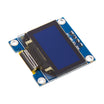
- 0.96" I2C OLED (SSD1306) - shows inductance in uH or mH
- Resistor Kit - provides 150 ohm and 1k ohm resistors
- 830-Point Breadboard - easy prototyping for the LC and comparator circuit
- Dupont Jumper Wires - wiring between the Nano, OLED, and LM339
External
- LM339 quad comparator (DIP-14)
- 2.2 uF film (polyester/MKT) capacitor - must be non-polarized, not electrolytic
- 1N4007 (or 1N4148) diode
- A few coils to test: a 100 uH axial inductor, a toroid, a salvaged transformer winding
Note: the tank capacitor’s real value drives the meter’s accuracy. Film capacitors are typically ±5 to 10%. If you built our capacitance meter, measure it and enter the exact number into the sketch. An electrolytic will not work because the tank swings below ground on every cycle.
Step-by-Step Guide
Step 1 - Build the Tank and Pulse Circuit
Goal: Create an LC tank the Arduino can kick.
What to do: Pick a breadboard row as the “tank node”. Connect the 2.2 uF capacitor from the node to GND. Connect the unknown coil from the node to GND (two clip leads make handy probes).
What to do: Build the pulse path: D13 to 150 ohm to diode anode, diode cathode to the tank node. The diode lets the pulse charge the tank, then disconnects so the tank can ring freely.
Expected result: The coil and capacitor are in parallel, fed through a one-way gate from D13.
Step 2 - Add the Comparator
Goal: Convert a decaying sine wave into square pulses the Arduino can time.
What to do: Power the LM339: pin 3 (VCC) to 5V, pin 12 (GND) to GND.
What to do: Wire comparator 1: pin 5 (IN+) to the tank node, pin 4 (IN-) to GND, pin 2 (OUT) to D11. Add a 1k ohm pull-up from pin 2 to 5V (the LM339 output is open-collector; without the pull-up it never goes HIGH).
What to do: Wire the OLED: SDA to A4, SCL to A5, VCC to 5V, GND to GND.
Expected result: Each time the tank swings above 0 V the comparator output is HIGH, and each HIGH pulse lasts half a period.
Step 3 - Upload the Sketch
Goal: Time the ringing and compute inductance from frequency.
Code:
#include <Adafruit_GFX.h>
#include <Adafruit_SSD1306.h>
Adafruit_SSD1306 oled(128, 64, &Wire, -1);

const int PULSE = 13, SENSE = 11;
const double C = 2.2e-6;                     // tank capacitor in farads: enter the measured value

double readInductance() {
  digitalWrite(PULSE, HIGH); delay(5);       // charge the tank
  digitalWrite(PULSE, LOW);  delayMicroseconds(100);
  double half = pulseIn(SENSE, HIGH, 5000);  // one HIGH pulse = half a period, in microseconds
  if (half == 0) return -1;                  // nothing rang: no coil, or out of range
  double f = 1.0 / (2.0 * half * 1e-6);      // resonant frequency in Hz
  return 1.0 / (4.0 * PI * PI * f * f * C);  // L = 1 / (4 pi^2 f^2 C), in henries
}

void setup() {
  pinMode(PULSE, OUTPUT); pinMode(SENSE, INPUT);
  oled.begin(SSD1306_SWITCHCAPVCC, 0x3C);
  oled.setTextColor(SSD1306_WHITE);
}

void loop() {
  double sum = 0; int n = 0;
  for (int i = 0; i < 10; i++) {             // average ten kicks
    double L = readInductance();
    if (L > 0) { sum += L; n++; }
  }
  oled.clearDisplay();
  oled.setTextSize(2); oled.setCursor(0, 0); oled.print("Inductance");
  oled.setCursor(0, 30);
  if (n == 0) oled.print("no coil");
  else {
    double L = sum / n;
    if (L < 1e-3) { oled.print(L * 1e6, 1); oled.print(" uH"); }
    else          { oled.print(L * 1e3, 2); oled.print(" mH"); }
  }
  oled.display();
  delay(300);
}
What to do: Install Adafruit GFX and Adafruit SSD1306, upload the sketch, then clip a 100 uH inductor between the probes (tank node to GND).
Expected result: The OLED reads close to “100.0 uH” and settles within about a second. Disconnect the coil and it shows “no coil”. A 10 mH choke reads in mH.
Step 4 - Calibrate
Goal: Improve accuracy by correcting the capacitor value.
What to do: Inductance is proportional to 1/C, so a 10% capacitor error becomes a 10% reading error. Either measure the capacitor and enter the measured value in the sketch, or measure a known inductor (for example a 5% axial part) and scale C until the reading matches.
What to do: Keep probe leads short (long leads add inductance). Coils with iron or ferrite cores can read slightly differently at this test frequency than at their rated frequency.
Expected result: Readings within a few percent from about 5 uH up to about 100 mH.
Step 5 - Understand and Extend
Goal: Understand the measurement and optional improvements.
What to do: The math is the resonance equation rearranged: f = 1 / (2π√(LC)). The comparator is key: the ringing decays quickly, but pulseIn() only needs one clean half-cycle.
What to do: You can swap in a 100 nF capacitor to push the low end below 1 uH (higher frequency and shorter pulses, so watch pulseIn()’s practical floor of about 10 us). You can also print the resonant frequency to quickly check a coil-capacitor pair for a filter or a crystal radio.
Expected result: A meter that makes junk-box coils usable.
Conclusion
A capacitor, a diode, a comparator, and one line of physics turn an Arduino Nano into a practical inductance meter. With the LM339 cleaning up the tank waveform and the SSD1306 OLED displaying the result, you can quickly label coils and sort unknown parts from about 5 uH to 100 mH.
Want the exact parts used in this build? Grab them from ShillehTek.com. If you want help customizing this project or building something for your product, check out our IoT consulting services.
Credit: Photos and the reference design are credited to carlosvolt on Hackster.io (LGPL license). The original guide by carlosvolt served as the reference for this ShillehTek version.






.png?v=25000753014097803521791168436)

.png?v=68677308723310773341791168436)


