

Project Overview
Arduino Binary Clock: Build an Arduino Nano + DS3231 RTC binary clock where 12 LEDs display the hour and minute in binary, plus a blinking seconds heartbeat LED. The DS3231 keeps accurate time and preserves it through power cuts with its coin cell, so the Nano only needs to read the time and light the correct bits.
A clock nobody else in the house can read is a very satisfying object. Along the way you will learn to read binary at a glance, and you can optionally mount it in a simple wooden or acrylic enclosure for a shelf-ready finish.
- Time: ~45 minutes (plus the enclosure if you build one)
- Skill level: Beginner
- What you will build: A battery-backed 24-hour binary clock with a seconds heartbeat, set automatically from your computer's clock on the first upload.

Parts List
From ShillehTek
- Arduino Nano V3.0 Pre-Soldered - runs the sketch and drives the LEDs
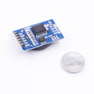
- DS3231 Precision RTC Module (with CR2032) - keeps accurate time with battery backup
- Arduino Uno R3 Super Starter Kit - includes LEDs in several colours
- Resistor Kit - 220Ω x12 for current limiting
- 830-Point Breadboard - quick prototyping
- Dupont Jumper Wires - easy connections on the breadboard
External
- Twelve 5 mm LEDs (two colours make the hour and minute rows easier to read)
- Optional: a plywood or acrylic front panel with twelve 5 mm holes
Note: the DS3231 module includes a CR2032 backup cell, so the time survives unplugging. Some modules ship with a rechargeable LIR2032 and a charging resistor. If yours has a non-rechargeable CR2032 and you power the module from 5 V, snip the charging diode/resistor as the module's documentation describes, or just use it as-is for a few years and replace the cell.
Step-by-Step Guide
Step 1 - Wire the LED Rows
Goal: Connect twelve LED outputs to twelve Arduino Nano pins.
What to do: Wire the hour row (five LEDs, values 16-8-4-2-1 from left to right): anodes to D2, D3, D4, D5, D6. Wire the minute row (six LEDs, values 32-16-8-4-2-1): anodes to D7, D8, D9, D10, D11, D12. Wire the seconds LED anode to D13.
For every LED, connect the cathode through its own 220Ω resistor to GND. Keep the rows physically aligned so the place values line up.

Expected result: Two rows of LEDs plus a heartbeat LED, all wired to their own pins.
Step 2 - Add the RTC
Goal: Add battery-backed timekeeping with a DS3231.
What to do: Connect the DS3231 module: SDA to A4, SCL to A5, VCC to 5V, and GND to GND.
In the Arduino IDE, install the RTClib library by Adafruit from the Library Manager.
Expected result: The RTC's red power LED (if present) lights.
Step 3 - Upload the Sketch
Goal: Read time from the DS3231 and display it in binary on the LEDs.
What to do: Paste this sketch into the Arduino IDE and upload it to your Nano.
Code:
#include <Wire.h>
#include <RTClib.h>
RTC_DS3231 rtc;

const int HOUR_PINS[5] = {2, 3, 4, 5, 6};        // place values 16 8 4 2 1
const int MIN_PINS[6]  = {7, 8, 9, 10, 11, 12};  // place values 32 16 8 4 2 1
const int TICK = 13;                             // blinks once a second

void showBits(const int* pins, int n, int value) {   // MSB on the left-most LED
  for (int i = 0; i < n; i++) digitalWrite(pins[i], (value >> (n - 1 - i)) & 1);
}

void setup() {
  for (int i = 0; i < 5; i++) pinMode(HOUR_PINS[i], OUTPUT);
  for (int i = 0; i < 6; i++) pinMode(MIN_PINS[i], OUTPUT);
  pinMode(TICK, OUTPUT);
  rtc.begin();
  if (rtc.lostPower()) {                                     // fresh module or dead cell:
    rtc.adjust(DateTime(F(__DATE__), F(__TIME__)));          // set from the time this sketch was compiled
  }
  // to set the time by hand once, uncomment, upload, then comment out and upload again:
  // rtc.adjust(DateTime(2026, 9, 13, 21, 45, 0));
}

void loop() {
  DateTime now = rtc.now();
  showBits(HOUR_PINS, 5, now.hour());        // 0..23
  showBits(MIN_PINS, 6, now.minute());       // 0..59
  digitalWrite(TICK, now.second() % 2);      // heartbeat
  delay(200);
}
On the first run, the sketch detects the RTC has no valid time and sets it from your computer's clock at compile time (a few seconds slow is normal).
Expected result: The rows light up in a pattern and the seconds LED blinks. Unplug the Nano for a minute and plug it back in: the time is still right.
Step 4 - Learn to Read It
Goal: Read hours and minutes from the binary LED patterns.
What to do: Add up the place values of the lit LEDs in each row. If you write a lit LED as 1 and a dark one as 0: hour row 1 0 1 0 1 = 16 + 4 + 1 = 21; minute row 1 0 1 1 0 1 = 32 + 8 + 4 + 1 = 45. So it is 21:45.
Prefer 12-hour time? Replace the hour line with int h = now.hour() % 12; if (h == 0) h = 12; showBits(HOUR_PINS, 5, h);. You will only ever use the four right-hand hour LEDs.
Expected result: You can read your clock; visitors cannot.
Step 5 - Box It
Goal: Move from a breadboard prototype to a finished display.
What to do: Drill twelve 5 mm holes in a panel in two rows (five above six, right-aligned so place values line up). Push the LEDs through and secure them from behind, then solder the resistors to a strip of perfboard. Power it from a phone charger.
For a dimmer night-time display, drive the LEDs from PWM pins or add a light sensor (KY-018) and lower brightness after dark. You can also add a button to step the minutes for the odd correction, though a DS3231 typically drifts only about two minutes a year.
Expected result: A finished clock that starts a conversation every time someone asks what it is.
Conclusion
You built an Arduino Nano binary clock using a DS3231 RTC module and 12 LEDs to show the hour and minute in binary with a blinking seconds heartbeat. With the DS3231 battery backup, the time stays correct even after unplugging.
Want the exact parts used in this build? Grab them from ShillehTek.com. If you want help customizing this project or building something for your product, check out our IoT consulting services.
Photos and the original project reference are credited to Kalle Wallin (silverskin) on Hackster.io.







.png?v=25000753014097803521791168436)

.png?v=68677308723310773341791168436)


