

Project Overview
DIY Arduino Metal Detector: Build an Arduino Nano metal detector using a Colpitts oscillator and frequency counting to detect metal by measuring small shifts around ~260 kHz. A blue LED indicates ready, green indicates a nearby target, and red plus the buzzer indicates a strong target signal.
- Time: 2-3 hours (coil winding included)
- Skill level: Intermediate
- What you will build: A frequency-shift metal detector with auto-calibrating baseline, three-stage LED indication, and audio alert.

Parts List
From ShillehTek
- Arduino Nano V3.0 Pre-Soldered - reads the oscillator signal on D5 and drives the LEDs and buzzer
- Resistor Kit - for the oscillator bias network and LED resistors
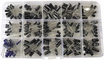
- 200PCS Electrolytic Capacitor Kit - coupling and supply filtering (tank caps are small ceramics, see External)
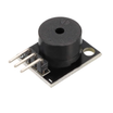
- KY-006 Passive Buzzer - audio alert when the frequency shift is large
- 400-Point Breadboard - quick prototyping for the oscillator and indicators
- Dupont Jumper Wires - breadboard and Arduino interconnects
External
- ~20 m of enameled magnet wire for the search coil (0.3-0.5 mm)
- One NPN transistor (2N2222/BC547), a few nF-range ceramic capacitors for the tank, and 3 LEDs (blue/green/red)
- Something round, ~20 cm across, to wind the coil on
Note: The search coil is about 25 turns of wire around a 20 cm form. Anywhere from roughly 200-400 µH works, which is why this design is forgiving to build.
Step-by-Step Guide
Step 1 - Wind the Coil
Goal: Make the sensing element.
What to do: Wrap about 25 turns of magnet wire around a 20 cm circular form (a bucket lid works well). Tape the bundle, then sand the enamel off the two wire ends so you have clean electrical contact.
This coil is the inductor in a resonant circuit. Its magnetic field extends out in front of the coil and becomes your detection zone.
Expected result: A search coil with two clean leads.
Step 2 - Build the Colpitts Oscillator
Goal: Make the coil oscillate around ~260 kHz.
What to do: Use one NPN transistor with the coil and a pair of tank capacitors to form a Colpitts oscillator. Use a coupling capacitor to tap the oscillator output to the Arduino input on D5.
When metal enters the coil's field, it changes the effective inductance and the oscillation frequency shifts. Measuring that shift is the detection principle.

Expected result: A steady RF signal on D5 that you cannot hear directly, but the Arduino can count.
Step 3 - Count the Frequency
Goal: Convert frequency shift into LED and buzzer alerts.
What to do: Install the FreqCount library and wire the indicators: buzzer to D12, blue LED to A2, green LED to A4, and red LED to A5. The sketch counts pulses in 100 ms windows, maintains a slowly adapting baseline, and triggers outputs based on how far the current reading is from that baseline.
Code:
#include <FreqCount.h>

const int BUZZ = 12, BLUE = A2, GREEN = A4, RED = A5;
long baseline = 0;

void setup() {
  pinMode(BUZZ, OUTPUT);
  pinMode(BLUE, OUTPUT); pinMode(GREEN, OUTPUT); pinMode(RED, OUTPUT);
  FreqCount.begin(100);              // count pulses per 100 ms on D5
}

void loop() {
  if (!FreqCount.available()) return;
  long f = FreqCount.read();

  if (baseline == 0) baseline = f;   // first reading
  long diff = abs(f - baseline);

  digitalWrite(BLUE,  diff <= 1);             // quiet: on target baseline
  digitalWrite(GREEN, diff > 1 && diff <= 5); // small shift: metal near
  digitalWrite(RED,   diff > 5);              // big shift: metal HERE

  if (diff > 5) tone(BUZZ, 800 + diff * 20, 90);   // pitch tracks strength

  baseline = (baseline * 15 + f) / 16;  // slow auto-recalibration
}
Expected result: Wave a coin over the coil. Green should flicker at distance, and red plus a rising buzzer tone should trigger as the coin gets closer.
Step 4 - Understand the Auto-Baseline
Goal: Understand why the detector does not need a manual tune knob.
What to do: The rolling average baseline (15/16 old + 1/16 new) allows slow drift from temperature and component aging, but it is slow enough that a fast frequency change caused by nearby metal still triggers the alerts.
Expected result: A detector that stays calibrated by itself during normal use.
Step 5 - Take It Outside
Goal: Move from a bench test to real scanning.
What to do: Mount the coil on a broomstick, then zip-tie the breadboard and a battery pack to the shaft. Sweep the yard. Coins should show up a few centimeters out, and larger iron objects from farther away. Adjust the two diff thresholds in code to match your coil and soil conditions.
Expected result: Detect real buried metal (bottle caps are likely).
Conclusion
This Arduino Nano metal detector combines a hand-wound search coil and simple Colpitts oscillator with frequency counting and a slow auto-baseline to detect metal through measurable frequency shift. The result is a practical detector with clear LED states and an audio alert.
Photo and circuit image credit: Mirko Pavleski on Hackster.io, whose original guide was used as a reference for this ShillehTek version.
Want the exact parts used in this build? Grab them from ShillehTek.com. If you want help customizing this project or building something for your product, check out our IoT consulting services.






.png?v=25000753014097803521791168436)

.png?v=68677308723310773341791168436)


