

Project Overview
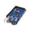
Arduino Mega 2560 + HC-05 Bluetooth module: Build a multi-UART serial router that forwards commands from your PC (USB Serial) and a phone (Bluetooth) to an Arduino Uno, then echoes the Uno replies back to both.
An Uno has one hardware serial port and it is busy talking to your computer, which is why GPS, Bluetooth, or second-board projects on an Uno often end up fighting with SoftwareSerial. The Mega 2560 has four hardware UARTs. In this build, the Mega routes commands from the USB Serial Monitor to an Uno over Serial1, then adds an HC-05 on Serial2 so the same commands can arrive from your phone. The Uno replies flow back to both.
- Time: ~45 minutes
- Skill level: Beginner
- What you will build: A Mega serial router that controls an Uno LED from USB or Bluetooth and echoes the Uno status back to both using three UARTs at once.

Parts List
From ShillehTek
- Mega 2560 R3 (CH340) Board - the main hub with four hardware UARTs
- Arduino Uno R3 Super Starter Kit - the second board being controlled
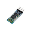
- HC-05 Bluetooth Module - Bluetooth serial link on Serial2
- Resistor Kit - 1kΩ + 2kΩ for the HC-05 RX voltage divider
- 830-Point Breadboard - easy wiring for the divider and module connections
- Dupont Jumper Wires - interconnect the Mega, Uno, and HC-05
External
- Two USB cables (one per board) and a phone with a Bluetooth serial terminal app (for Step 5)
Note: The Mega Serial (pins 0 and 1) is wired to the USB interface. If you put a module on pins 0 and 1 you can interfere with uploads. Use Serial1, Serial2, and Serial3 for external devices and leave Serial for the PC.
Step-by-Step Guide
Step 1 - Know the four ports
Goal: Learn the Mega 2560 serial pin map you will use for wiring.
What to do: The Mega 2560 has four hardware UARTs:
-
Serialon pins 0 (RX0) and 1 (TX0), shared with USB -
Serial1on 19 (RX1) and 18 (TX1) -
Serial2on 17 (RX2) and 16 (TX2) -
Serial3on 15 (RX3) and 14 (TX3)
Each port is interrupt-driven with its own buffers and is full duplex. SoftwareSerial is bit-banged, can block, and on the Mega only supports RX on certain pins (10 to 15, 50 to 53, A8 to A15). Use it only when you truly run out of hardware ports.
Expected result: You know that Serial2 means pins 16 and 17 without looking it up.
Step 2 - Wire the Mega to the Uno
Goal: Create a hardware serial link between the two boards using Serial1.
What to do: Wire the Mega to the Uno like this:
- Mega pin 18 (TX1) to Uno pin 0 (RX)
- Mega pin 19 (RX1) to Uno pin 1 (TX)
- Mega GND to Uno GND
Transmit goes to receive (crossed TX/RX), and grounds must be connected so both boards share a signal reference. Power each board from its own USB cable for now.
Expected result: Three wires between the boards.
Step 3 - Upload the Uno sketch (the listener)
Goal: Make the Uno respond to simple serial commands and report status.
What to do: Upload this to the Uno. Disconnect the wires from Uno pins 0 and 1 while uploading, then reconnect them afterward.
Code:
// Upload to the UNO. Pull the wires off pins 0 and 1 while uploading, then put them back.
const int LED = 13;

void setup() {
  Serial.begin(9600);
  pinMode(LED, OUTPUT);
}

void loop() {
  if (Serial.available()) {
    char c = Serial.read();
    if (c == 'a')      { digitalWrite(LED, HIGH); Serial.println("UNO: LED on"); }
    else if (c == 'x') { digitalWrite(LED, LOW);  Serial.println("UNO: LED off"); }
  }
}
Select Arduino Uno and the correct port, upload, then reconnect Uno pins 0 and 1 to the Mega.
Expected result: The Uno waits for single characters and replies with a status line.
Step 4 - Upload the Mega sketch (the router)
Goal: Forward commands from USB serial and Bluetooth serial to the Uno, then broadcast the Uno replies back to both.
What to do: Upload this to the Mega.
Code:
// Upload to the MEGA. USB (Serial) and Bluetooth (Serial2) in, Uno (Serial1) out; Uno replies go to both.
void setup() {
  Serial.begin(9600);    // USB to the PC
  Serial1.begin(9600);   // pins 18 (TX1) / 19 (RX1) -> Uno
  Serial2.begin(9600);   // pins 16 (TX2) / 17 (RX2) -> HC-05 (its default is 9600) - harmless if not wired yet
  Serial.println("MEGA router ready: send a (LED on) or x (LED off)");
}

void loop() {
  if (Serial.available()) {                 // command from the PC
    char c = Serial.read();
    Serial1.write(c);
    Serial.print("USB -> UNO: "); Serial.println(c);
  }
  if (Serial2.available()) {                // command from the phone
    char c = Serial2.read();
    Serial1.write(c);
    Serial.print("BT  -> UNO: "); Serial.println(c);
  }
  while (Serial1.available()) {             // whatever the Uno says goes to both
    char c = Serial1.read();
    Serial.write(c);
    Serial2.write(c);
  }
}
Select Arduino Mega or Mega 2560, upload, open Serial Monitor at 9600 with No line ending, then send a and x.
Expected result: You see messages like USB -> UNO: a, the Uno LED toggles, and UNO: LED on returns through the Mega.
Step 5 - Add the HC-05 on Serial2
Goal: Send the same commands from a phone over Bluetooth.
What to do: Wire the HC-05 like this:
- HC-05 VCC to Mega 5V
- HC-05 GND to Mega GND
- HC-05 TXD to Mega pin 17 (RX2) directly
- HC-05 RXD from Mega pin 16 (TX2) through a divider: 1kΩ from pin 16 to HC-05 RXD, and 2kΩ from HC-05 RXD to GND
The HC-05 TXD is 3.3 V logic, which is read as HIGH by the Mega. The HC-05 RXD expects 3.3 V logic, which is why the divider is used on the Mega TX2 line.
Pair your phone with the HC-05 (PIN 1234 or 0000), open a Bluetooth serial terminal app, and send a and x.
Expected result: The Uno LED obeys the phone, the Serial Monitor shows BT -> UNO: a, and the Uno reply appears on the phone too.
Step 6 - Serial3 and beyond
Goal: Understand how to extend the same approach to more serial devices.
What to do: You can add another device on Serial3 (pins 14 and 15), such as a GPS module, while still bridging the Uno and the phone. Consider upgrading the Uno protocol from single letters to line-based commands (for example LED,1 parsed with Serial.readStringUntil('\n')). You can also swap the HC-05 for a different serial device (such as an ESP-01) on Serial2. If you truly need a fifth serial port, that is when SoftwareSerial becomes relevant, using a Mega-compatible RX pin (10 or above).
Expected result: A clear plan for using the Mega as a multi-device serial hub.
Conclusion
By crossing TX and RX, sharing ground, and choosing the right Mega UART, you can run USB serial, Bluetooth serial, and an Uno link at the same time without SoftwareSerial workarounds. In this build, the Arduino Mega 2560 routes commands to the Uno over Serial1 and adds the HC-05 on Serial2 so both your PC and phone can control the same sketch.
Want the exact parts used in this build? Grab them from ShillehTek.com. If you want help customizing this project or building something for your product, check out our IoT consulting services.
Credits: Photos and the original reference guide are credited to Alex Fraga (BlueShark) on Hackster.io (Apache-2.0 license).






.png?v=25000753014097803521791168436)

.png?v=68677308723310773341791168436)


