

Project Overview
Arduino + KY-026 Flame Sensor: In this project you build an optical flame alarm where the KY-026 sensor watches for flame radiation, the Arduino reads its analog output, and a buzzer sounds when combustion is detected.
This is a practical early-warning device for a workshop, 3D-printer corner, or electronics bench.
- Time: About 45 minutes
- Skill level: Beginner
- What you will build: An optical flame alarm that sounds a buzzer when it sees fire.

Parts List
From ShillehTek
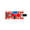
- KY-026 Flame Sensor Module - detects flame radiation and outputs analog and digital signals.
- Arduino Nano V3 - reads the sensor and triggers the alarm (or any Arduino UNO-compatible board).
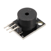
- KY-006 Passive Piezo Buzzer Module - audible alarm output.
- 120pcs 20cm Dupont Jumper Wires - easy no-solder wiring.
External
- USB cable for programming
- A lighter or candle for careful testing
Note: Never leave an open flame unattended while testing, and keep the sensor at a safe distance. It detects flames optically, so it does not need to be close.
Step-by-Step Guide
Step 1 - Why build a flame detector
Goal: Understand what this device protects against.
What to do: Fire hazards go beyond burns. Smoke inhalation is serious, and property damage compounds quickly. Optical flame sensors are used on machinery that can spark fires because early detection buys time. This build applies the same idea to a small electronics setup.
Expected result: A clear goal: detect combustion light early and alarm immediately.
Step 2 - Meet the KY-026 module
Goal: Know the sensor's capabilities.
What to do: The KY-026 detects flame radiation and ordinary light sources in the 760 to 1100 nm wavelength range with a detection cone of roughly 60 degrees. It runs from 3.3 to 5V and provides two outputs: a digital pin (0/1, threshold set by the blue potentiometer) driven by an LM393 comparator, and an analog pin (A0) with the raw intensity. A lighter flame may be detectable from around 80 cm. Keep distance between the sensor and any flame so heat cannot damage it.

Expected result: You know which output to use: this guide reads the analog AO pin for finer control.
Step 3 - Understand the flame spectrum
Goal: Know why the sensor sees fire reliably.
What to do: When carbon-based material burns in oxygen, its emission spectrum shows two signature peaks: one in the ultraviolet at 185 to 260 nm and one in the infrared around 4400 to 4600 nm. Optical flame detectors are tuned to these signatures. Industrial detectors often combine UV and IR channels for certainty.

Expected result: You understand the physics your alarm relies on.
Step 4 - Gather the hardware
Goal: Lay out the main components.
What to do: You need the flame sensor module, an Arduino, a buzzer for the alarm, and a handful of jumper wires.


Expected result: All parts are ready on the bench.
Step 5 - Wire the circuit
Goal: Connect the sensor and buzzer to the Arduino.
What to do: Connect the KY-026 analog output to A0, VCC to 5V, and GND to GND. Connect the buzzer positive lead to digital pin 11 and its negative lead to GND.
KY-026 AO  -> A0     KY-026 VCC (+) -> 5V     KY-026 GND (G) -> GND
Buzzer (+) -> D11    Buzzer (-) -> GND
Expected result: A two-module circuit ready for code.
Step 6 - Upload the source code
Goal: Read the flame signal and drive the alarm.
What to do: Upload this sketch. It prints the analog value continuously. When a flame is detected, the reading drops below the threshold (500 here) and the buzzer pulses. Use the Serial Monitor to observe your sensor's idle value and tune the threshold accordingly.
Code:
int buzzer = 11;      // buzzer pin
int valorSensor = 0;  // value coming from the sensor

void setup() {
  Serial.begin(9600);
  pinMode(buzzer, OUTPUT);
}

void loop() {
  // Read the flame sensor's analog value
  valorSensor = analogRead(A0);
  Serial.println(valorSensor);

  // Sound the alarm when a flame is detected
  if (valorSensor < 500) {
    digitalWrite(buzzer, HIGH);
    delay(100);
    digitalWrite(buzzer, LOW);
    delay(50);
  }
}
Expected result: Idle readings stream in the Serial Monitor. Bringing a small flame near the sensor (carefully) makes the value drop and the buzzer chirp rapidly.
Conclusion
You built an Arduino-based optical flame detector using the KY-026 flame sensor module. The Arduino reads the analog signal on A0 and triggers a buzzer alarm when the reading drops below a set threshold.
Photo credits: images in this tutorial are credited to Instructables (original guide by CarlosVoltT), which served as the reference for this ShillehTek version.
Want the exact parts used in this build? Grab them from ShillehTek.com. If you want help customizing this project or building something for your product, check out our IoT consulting services.




.png?v=25000753014097803521791168436)

.png?v=68677308723310773341791168436)


