

Project Overview
Arduino water flow meter with a G1/2 inch hall-effect flow sensor: A G1/2 inch hall-effect flow sensor screws inline with any half-inch pipe or hose and outputs pulses as water spins its internal rotor. Count those pulses with an Arduino interrupt to calculate live flow rate (L/min) and accumulated total volume (liters) for irrigation controllers, water-usage monitors, and leak detectors.
- Time: ~45 minutes
- Skill level: Beginner
- What you will build: An inline water meter showing L/min and total liters on the Serial Monitor (with an optional LCD readout).

Parts List
From ShillehTek
- ZJ-S201 Water Flow Sensor G1/2" (1–30 L/min) - hall-effect sensor that outputs pulses proportional to water flow
- Arduino Uno R3 - reads pulses via an interrupt pin and calculates flow and total volume
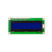
- LCD1602 16x2 Display - optional at-a-glance readout
- 400-Point Breadboard - makes prototyping the connections easier
- Dupont Jumper Wires - connects the sensor (and optional LCD) to the Arduino
External
- G1/2 inch hose fittings or pipe adapters for your plumbing
Note: Inside the sensor, water spins a rotor holding a magnet; a hall-effect sensor outside the water path counts each pass. Nothing electrical ever touches the water - the housing is sealed, rated 1–30 L/min.
Step-by-Step Guide
Step 1 - Wire the Sensor
Goal: Connect the three sensor wires and use an interrupt-capable pin for the signal.
What to do: Connect red to 5V, black to GND, and the yellow signal wire to digital pin 2. Pin 2 matters because it is one of the Arduino Uno hardware-interrupt pins, which lets the Arduino count every pulse even while the rest of your sketch is busy. Mount the sensor with the flow arrow pointing the direction the water actually moves.

Expected result: The sensor is mounted inline and wired to the Arduino.
Step 2 - Understand the Math
Goal: Convert pulse counts into liters per minute and total liters.
What to do: These G1/2 inch hall sensors follow a simple characteristic: pulse frequency (Hz) ≈ 7.5 × flow rate (L/min). So if the interrupt counts 75 pulses in one second, water is moving at 10 L/min. Divide the rate by 60 for liters-per-second and add it up every second to track total volume. Every flow sensor varies a few percent, so calibrate by timing how long it takes to fill a known container and scaling the 7.5 factor to match.
Expected result: You can convert any pulse count into a flow rate and volume estimate.
Step 3 - Upload the Flow Meter Sketch
Goal: Print live flow rate and a running total to the Serial Monitor.
What to do: The interrupt increments a counter on every rising edge; the loop does the math once per second.
Code:
volatile unsigned int pulseCount = 0;

const byte FLOW_PIN = 2;      // must be an interrupt pin
const float CAL     = 7.5;    // pulses/sec per L/min (tune to your sensor)

float flowRate = 0.0;         // L/min
float totalLiters = 0.0;
unsigned long lastCalc = 0;

void pulseISR() {
  pulseCount++;
}

void setup() {
  Serial.begin(9600);
  pinMode(FLOW_PIN, INPUT_PULLUP);
  attachInterrupt(digitalPinToInterrupt(FLOW_PIN), pulseISR, RISING);
  lastCalc = millis();
}

void loop() {
  if (millis() - lastCalc >= 1000) {
    noInterrupts();
    unsigned int pulses = pulseCount;
    pulseCount = 0;
    interrupts();

    flowRate = pulses / CAL;              // L/min
    totalLiters += flowRate / 60.0;       // liters added this second

    Serial.print("Rate: ");
    Serial.print(flowRate);
    Serial.print(" L/min   Total: ");
    Serial.print(totalLiters);
    Serial.println(" L");

    lastCalc = millis();
  }
}
Expected result: Open the Serial Monitor, run water through the sensor, and watch rate and total climb in real time.
Step 4 - Add the LCD (Optional)
Goal: Show flow and total on a standalone display (no computer needed).
What to do: Wire the LCD1602 in classic 4-bit mode (RS to 12, E to 11, D4-D7 to 5, 4, 3, 9, contrast pot on V0) and print the same two numbers using the LiquidCrystal library: rate on line one, total on line two. Now the meter works anywhere there is 5V.
Expected result: A display like "Rate: 10.4 L/M / Vol: 37.2 L" updates as water flows.
Step 5 - Put It to Work
Goal: Apply this sensor reading technique to real projects.
What to do: Install it inline with a garden hose to measure exactly how much water your irrigation run uses; pair it with a relay and shut a valve after N liters; log totals to an SD card or push them over WiFi for a household water dashboard; or watch for flow when everything should be off for a low-cost leak detector.
Expected result: A reusable water-metering building block you can integrate into automation and monitoring projects.
Conclusion
One inline sensor, one interrupt pin, and one formula (about 7.5 Hz per L/min) turn an Arduino Uno into a practical water meter with live flow rate and cumulative total liters. This beginner-friendly build scales into irrigation automation, usage dashboards, and leak alarms.
Want the exact parts used in this build? Grab them from ShillehTek.com. If you want help customizing this project or building something for your product, check out our IoT consulting services.
Image credit: Photos and diagrams referenced from Sheekar Banerjee on Hackster.io.






.png?v=25000753014097803521791168436)

.png?v=68677308723310773341791168436)


