

Project Overview
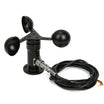
Arduino + analog anemometer: In this project, you wire a 3-wire 0 to 5V analog output anemometer to an Arduino and convert its voltage into wind speed readings shown live in the Serial Monitor.
Anemometers measure wind speed by using spinning cups to drive a sensor that outputs an analog voltage proportional to airflow. This is a classic first building block for a DIY weather station.
- Time: 30-45 minutes
- Skill level: Beginner
- What you will build: A live wind-speed readout from a cup anemometer on the Arduino Serial Monitor.
Parts List
From ShillehTek
- Wind Speed Sensor Anemometer with 0-5V Analog Output - provides an analog voltage proportional to wind speed
- Arduino Nano V3 - or any Arduino UNO-compatible board for reading the analog signal
- 120pcs 20cm Dupont Jumper Wires - three male-to-male jumpers for power, ground, and signal
External
- USB cable for the Arduino - for programming and Serial Monitor data
- 9V battery with snap connector - supplies the anemometer supply voltage through VIN
Note: Analog anemometers typically want a 7 to 24V supply and return a low analog voltage on the signal wire, which any Arduino analog pin can read safely. Check your unit's voltage-to-speed mapping and use it in the code constants.
Step-by-Step Guide
Step 1 - Prepare the Anemometer Cable
Goal: Turn the sensor's bare leads into breadboard-friendly connections.
What to do: The anemometer's cable carries three conductors: black (ground), brown (power, 7-24V), and blue (analog voltage output). Each lead has a short stripped end. Wrap each one tightly around the pin of a male-to-male jumper wire (match colors where you can) so all three strands extend into clean jumper ends.

Expected result: Three solid connections ready for the Arduino headers.
Step 2 - Connect to the Arduino
Goal: Route signal, power, and ground to the right pins.
What to do: Plug the three jumpers into the Arduino:
Blue  (signal)      ->  A0
Brown (power 7-24V) ->  VIN
Black (ground)      ->  GND
Expected result: The sensor shares ground with the Arduino and its signal feeds analog pin A0.
Step 3 - Power Everything
Goal: Give the anemometer the supply voltage it needs.
What to do: Connect the USB cable between the Arduino and your computer for data. Then snap the 9V battery onto its connector and feed the Arduino's power input. With the board running on the battery, the VIN pin carries roughly 9V, which is inside the anemometer's 7-24V supply range.
Expected result: Sensor powered from VIN, serial data flowing over USB.
Step 4 - Upload the Wind Speed Sketch
Goal: Convert the analog voltage into wind speed.
What to do: Upload this sketch (adapted from Joe Burg's hackerscapes anemometer code). It reads A0, converts the ADC count to volts, then maps the voltage linearly between the sensor's minimum (0.4V = no wind) and maximum (2.0V = full-scale wind). Adjust voltageMax and windSpeedMax to your sensor's datasheet.
int sensorPin = A0;
int sensorValue = 0;
float sensorVoltage = 0;
float windSpeed = 0;

float voltageConversionConstant = .004882814; // 5V / 1024 steps
int sensorDelay = 1000;

float voltageMin = .4;      // sensor voltage at zero wind
float windSpeedMin = 0;
float voltageMax = 2.0;     // sensor voltage at max rated wind
float windSpeedMax = 32;    // max rated wind speed

void setup() {
  Serial.begin(9600);
}

void loop() {
  sensorValue = analogRead(sensorPin);
  sensorVoltage = sensorValue * voltageConversionConstant;

  if (sensorVoltage <= voltageMin) {
    windSpeed = 0;
  } else {
    windSpeed = (sensorVoltage - voltageMin) * windSpeedMax / (voltageMax - voltageMin);
  }

  Serial.print("Voltage: ");
  Serial.print(sensorVoltage);
  Serial.print("\t");
  Serial.print("Wind speed: ");
  Serial.println(windSpeed);
  delay(sensorDelay);
}
Expected result: The sketch compiles and uploads without errors.
Step 5 - Find Some Wind
Goal: Give the cups something to do.
What to do: Take the rig outside on a breezy day, point a fan at it, or blow on the cups to simulate wind.
Expected result: The cups spin freely and the output voltage climbs.
Step 6 - Read the Measurements
Goal: See live wind speed data.
What to do: Open the Serial Monitor (Tools Serial Monitor) at 9600 baud. You will see a voltage column and the computed wind speed side by side, updating once per second.
Expected result: Wind speed readings that rise and fall with the breeze. You can log them, graph them, or trigger alerts from them.
Conclusion
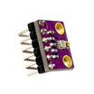
You connected an analog cup anemometer to an Arduino, powered it through VIN, and converted its output voltage into wind speed readings using a simple linear mapping in code. For a more complete weather station, you can pair it with a BME280 to measure temperature, humidity, and pressure.
Photo and reference credit: Instructables (original guide by CyberFantasies), with code adapted from Joe Burg's hackerscapes anemometer example.
Want the exact parts used in this build? Grab them from ShillehTek.com. If you want help customizing this project or building something for your product, check out our IoT consulting services.




.png?v=25000753014097803521791168436)

.png?v=68677308723310773341791168436)


