Overview
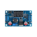
This is the XL4015 5A buck converter with an integrated 3-digit 7-segment voltmeter built right onto the board. Same 96%-efficient buck topology as the bare XL4015 module, but the onboard display means you can dial in your output voltage at a glance — no multimeter required.
A press of the small S1 button switches the display between input and output voltage, so you can verify both rails on one screen. Wide 4-38V input, 1.25-36V adjustable output, and 5A continuous current capability make this a workhorse for powering Pi clusters, motor controllers, LED arrays, and any project where you want a tunable rail with built-in monitoring.
At a Glance
Specifications
| Parameter | Value |
| IC | XL4015 |
| Topology | Step-down (buck) |
| Input Voltage | 4V - 38V DC |
| Output Voltage | 1.25V - 36V DC (adjustable via trimpot) |
| Output Current | 5A continuous (with cooling) |
| Output Power | 75W maximum |
| Conversion Efficiency | Up to 96% |
| Switching Frequency | 180 kHz |
| Display | 3-digit 7-segment LED voltmeter |
| Display Mode Button (S1) | Toggle IN / OUT voltage display |
| Display Accuracy | ±1% ±2 digits |
| Operating Temperature | -40°C to +85°C |
| Module Dimensions | ~62 × 32 × 14 mm |
Pinout Diagram

Wiring Guide
Basic Setup — Setting the Output
Always set the output BEFORE wiring the load. Power up with input only, watch the display in OUT mode, and turn the trimpot until you read your target voltage.
| Step | Action |
|---|---|
| 1 | Connect input source to IN+ / IN- (mind polarity) |
| 2 | Power on. Display lights up showing input voltage |
| 3 | Press S1 to toggle to OUT mode |
| 4 | Turn the brass-screw trimpot clockwise to raise output, CCW to lower |
| 5 | Once the display reads your target voltage, power down and connect your load |
Using the Voltmeter Display
The display reads in volts with one decimal place. Single press the S1 button to toggle between IN and OUT.
| Mode | Display | How to Switch |
|---|---|---|
| OUT | Output voltage (default) | Power on (default) |
| IN | Input voltage | Press S1 once |
| OUT | Output voltage | Press S1 again |
Power a Raspberry Pi from 12V
Set output to 5.1V (Pi 4 needs steady 5.1V to avoid undervoltage warnings). Confirm via the onboard display.
| Module Terminal | Connection |
|---|---|
| IN+ | 12V supply + |
| IN- | Supply ground |
| OUT+ | Pi 5V (GPIO Pin 2 or 4) |
| OUT- | Pi GND (Pin 6) |
Power LED Strips
| Strip Type | Output Setting | Notes |
|---|---|---|
| WS2812 (5V) | 5.0V | Add 1000µF cap across V/GND at strip start |
| WS2811 (12V) | 12.0V | Match input closely to minimize regulator load |
| Analog 12V strip | 12.0V | 5A is enough for ~5m of standard density |
Code Examples
The XL4015 is a passive analog regulator — there's no microcontroller-side code. The "code" is the trim potentiometer + display. Examples below show how to monitor the output rail from a microcontroller (useful for closed-loop battery management or undervoltage protection).
Arduino — Monitor Output via ADC
// Monitor XL4015 output rail with Arduino ADC
// Voltage divider: OUT+ -- 30k -- A0 -- 10k -- GND
// Divides up to 22V down to ~5.5V at A0 (Arduino 5V tolerant)

const int sensePin = A0;
const float DIV_RATIO = (30000.0 + 10000.0) / 10000.0;

void setup() { Serial.begin(9600); }

void loop() {
  int raw = analogRead(sensePin);
  float vAtPin = raw * (5.0 / 1023.0);
  float vRail = vAtPin * DIV_RATIO;
  Serial.print("Rail: "); Serial.print(vRail, 2); Serial.println(" V");
  delay(500);
}
ESP32 — Monitor with Internal ADC
// ESP32 - monitor XL4015 output rail
// Same divider, ADC1_CH0 = GPIO 36

const int sensePin = 36;
const float DIV_RATIO = 4.0;
const float VREF = 3.3;

void setup() {
  Serial.begin(115200);
  analogReadResolution(12);  // 0-4095
}

void loop() {
  int raw = analogRead(sensePin);
  float vAtPin = raw * (VREF / 4095.0);
  float vRail = vAtPin * DIV_RATIO;
  Serial.printf("Rail: %.2f V\n", vRail);
  delay(500);
}