Overview
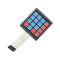
The 4×3 membrane matrix keypad is a low-profile flexible keypad with 12 buttons (digits 0-9 plus * and #) arranged in 4 rows and 3 columns — the same layout as a phone, calculator, or door access keypad. It connects to any microcontroller using just 7 GPIO pins (4 rows + 3 columns) and provides a clean way to take user input for menu navigation, PIN entry, calculator displays, security keypads, lock controls, or any application that needs numeric or numeric-plus-symbols input.
The keypad is constructed as a thin flexible PCB with conductive traces and silicone-rubber dome switches under each labeled key. Pressing a key shorts one row line to one column line; the microcontroller scans the matrix by driving rows LOW one at a time and reading the columns to detect which key is pressed. The popular Arduino Keypad library handles all of this with a single one-line read call.
Common uses: door entry / access control with PIN, simple calculators, digital safes, vending-machine simulators, garage-door openers, robot-arm command pads, IoT control panels, RFID-paired entry systems, and just about any project where 12 buttons in a phone-style layout is the right input.
At a Glance
Specifications
| Parameter | Value |
| Matrix Layout | 4 rows × 3 columns = 12 keys |
| Key Layout | 1 2 3 / 4 5 6 / 7 8 9 / * 0 # |
| Output | 7-pin ribbon cable, 2.54 mm (0.1") pitch female header |
| Pin Order (left-to-right facing the cable) | R1, R2, R3, R4, C1, C2, C3 |
| Switch Type | Tactile silicone-rubber dome, momentary, normally-open |
| Construction | Flexible membrane PCB with adhesive backing |
| Operating Force | ~150-250 gf |
| Bounce Time | < 5 ms typical |
| Contact Resistance | < 100 Ω |
| Insulation Resistance | > 100 MΩ @ 100V |
| Lifespan | ~1,000,000 actuations per key |
| Operating Temperature | -20°C to +60°C |
| Dimensions | ~70 × 77 mm (overall) |
Pinout Diagram

Wiring Guide
The 7-pin ribbon header connects to the microcontroller. Each row pin (R1-R4) and column pin (C1-C3) goes to a digital GPIO pin. The Keypad Arduino library handles scanning, debouncing, and decoding.
Arduino UNO Wiring
| Keypad Pin | Arduino Pin |
|---|---|
| R1 (pin 1) | D9 |
| R2 (pin 2) | D8 |
| R3 (pin 3) | D7 |
| R4 (pin 4) | D6 |
| C1 (pin 5) | D5 |
| C2 (pin 6) | D4 |
| C3 (pin 7) | D3 |
ESP32 / Raspberry Pi Pico
Any 7 free GPIO pins on either board work. Internal pull-ups should be enabled in software (the Keypad library does this).
| Keypad Pin | ESP32 | Pi Pico |
|---|---|---|
| R1 | GPIO13 | GP10 |
| R2 | GPIO12 | GP11 |
| R3 | GPIO14 | GP12 |
| R4 | GPIO27 | GP13 |
| C1 | GPIO26 | GP14 |
| C2 | GPIO25 | GP15 |
| C3 | GPIO33 | GP16 |
Code Examples
Read Keys (Arduino, Keypad library)
#include <Keypad.h>

const byte ROWS = 4;
const byte COLS = 3;

char keys[ROWS][COLS] = {
  {'1','2','3'},
  {'4','5','6'},
  {'7','8','9'},
  {'*','0','#'}
};

byte rowPins[ROWS] = {9, 8, 7, 6};   // R1..R4
byte colPins[COLS] = {5, 4, 3};       // C1..C3

Keypad keypad = Keypad(makeKeymap(keys), rowPins, colPins, ROWS, COLS);

void setup() {
  Serial.begin(9600);
}

void loop() {
  char key = keypad.getKey();
  if (key) {
    Serial.print("Pressed: ");
    Serial.println(key);
  }
}
4-Digit PIN Entry with Lockout
#include <Keypad.h>

const byte ROWS = 4, COLS = 3;
char keys[ROWS][COLS] = {
  {'1','2','3'},{'4','5','6'},{'7','8','9'},{'*','0','#'}
};
byte rowPins[ROWS] = {9,8,7,6};
byte colPins[COLS] = {5,4,3};
Keypad keypad = Keypad(makeKeymap(keys), rowPins, colPins, ROWS, COLS);

const String correct = "1234";
String entered = "";

void setup() { Serial.begin(9600); Serial.println("Enter 4-digit PIN, end with #"); }

void loop() {
  char k = keypad.getKey();
  if (k) {
    if (k == '#') {
      Serial.println(entered == correct ? "ACCESS GRANTED" : "DENIED");
      entered = "";
    } else if (k == '*') {
      entered = "";
      Serial.println("Cleared");
    } else {
      entered += k;
      Serial.print('*');
    }
  }
}