

Project Overview
RP2040-Zero + MPU6050 USB Mouse: Build a plug-and-play USB HID mouse from five tactile buttons on an RP2040-Zero, then add an MPU6050 to steer the cursor by tilting the board for simple air-mouse control.
The RP2040-Zero is a thumb-sized board with native USB, which means it can be a USB device instead of just talking to one. In this guide it becomes a mouse: five tactile buttons for up, down, left, right and click, recognized by any computer with no drivers, using the Arduino Mouse library on the RP2040 core.
Then we add an MPU6050 so tilting the board steers the cursor. The onboard WS2812 LED shows the click state, and the same skeleton works for a keyboard, a game controller, or an accessibility switch device.
- Time: ~1 hour
- Skill level: Beginner to Intermediate
- What you will build: A five-button USB HID mouse with optional MPU6050 tilt control and LED click feedback, programmed in the Arduino IDE.

Parts List
From ShillehTek
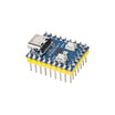
- RP2040-Zero Board (pre-soldered headers) - native USB for HID mouse behavior
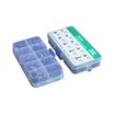
- Tactile Button Kit - five buttons for up/down/left/right/click
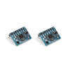
- MPU6050 Accelerometer/Gyro (pre-soldered) - optional tilt-to-move air mouse control
- 400-Point Breadboard - quick prototyping
- Dupont Jumper Wires - wiring between board, buttons, and IMU
External
- A USB-C cable that carries data (some charging-only cables do not)
Note: The RP2040-Zero has BOOT and RESET as tiny side buttons. For the very first upload, hold BOOT while you plug in USB (or tap RESET while holding BOOT). The board mounts as a drive called RPI-RP2 and the Arduino IDE uploads to it. After that first sketch, normal uploads work without any button.
Step-by-Step Guide
Step 1 - Install the RP2040 Core
Goal: Set up the Arduino IDE so it can program the RP2040-Zero and use USB HID libraries.
What to do: In File → Preferences → Additional Boards Manager URLs add https://github.com/earlephilhower/arduino-pico/releases/download/global/package_rp2040_index.json. In the Boards Manager install "Raspberry Pi Pico/RP2040" by Earle Philhower.
Select Tools → Board → Raspberry Pi Pico/RP2040 → Waveshare RP2040 Zero, and leave USB Stack on the default (Pico SDK). The Mouse and Keyboard libraries are built in. Also install Adafruit NeoPixel from the Library Manager for the onboard LED.
Expected result: Blink compiles and uploads (first time via the BOOT method described in the parts note, then normally).
Step 2 - Wire Five Buttons
Goal: Create a D-pad plus a click button using GPIO inputs.

What to do: Put five tactile buttons on the breadboard in a plus shape (up, left/right, down) with the click button off to the side. One leg of each button goes to GND; the other legs go to GP0 (up), GP1 (down), GP2 (left), GP3 (right), and GP4 (click).
No resistors are needed. The sketch enables the RP2040 internal pull-ups, so a pressed button reads LOW.
Expected result: Five GPIOs that each read HIGH at rest and LOW when pressed.
Step 3 - Upload the Mouse Sketch
Goal: Make the RP2040-Zero enumerate as a USB mouse and move the cursor using button presses.
What to do: Paste and upload the sketch below. The IDE may lose the serial port for a moment while the board re-enumerates as a mouse. That is normal.
#include <Mouse.h>
#include <Wire.h>
#include <Adafruit_NeoPixel.h>

const int BTN[5] = {0, 1, 2, 3, 4};   // GP0 up, GP1 down, GP2 left, GP3 right, GP4 click (other leg to GND)
const int STEP = 5;                   // pixels per loop while a button is held
const bool USE_IMU = false;           // set true after Step 5
const uint8_t MPU = 0x68;             // MPU6050 I2C address (AD0 low)

Adafruit_NeoPixel px(1, 16, NEO_GRB + NEO_KHZ800);   // RP2040-Zero onboard WS2812 on GP16

int16_t readAxis(uint8_t reg) {       // one 16-bit MPU6050 register pair
  Wire1.beginTransmission(MPU); Wire1.write(reg); Wire1.endTransmission(false);
  Wire1.requestFrom(MPU, (size_t)2);
  int hi = Wire1.read(); int lo = Wire1.read();
  return (int16_t)((hi << 8) | lo);
}

void setup() {
  for (int i = 0; i < 5; i++) pinMode(BTN[i], INPUT_PULLUP);
  px.begin(); px.setPixelColor(0, px.Color(0, 8, 0)); px.show();   // dim green = idle
  if (USE_IMU) {
    Wire1.setSDA(26); Wire1.setSCL(27); Wire1.begin();
    Wire1.beginTransmission(MPU); Wire1.write(0x6B); Wire1.write(0); Wire1.endTransmission();   // wake it up
  }
  Mouse.begin();
}

void loop() {
  bool up = !digitalRead(BTN[0]),   down  = !digitalRead(BTN[1]);
  bool left = !digitalRead(BTN[2]), right = !digitalRead(BTN[3]);
  bool click = !digitalRead(BTN[4]);

  int dx = (right - left) * STEP;
  int dy = (down - up) * STEP;

  if (USE_IMU) {                                   // tilt adds to the buttons
    float ax = readAxis(0x3B) / 16384.0;           // accel X in g
    float ay = readAxis(0x3D) / 16384.0;           // accel Y in g
    if (fabs(ax) > 0.15) dx += (int)(ax * 12);     // dead zone, then proportional to tilt
    if (fabs(ay) > 0.15) dy += (int)(ay * 12);
  }

  if (dx || dy) Mouse.move(dx, dy, 0);

  if (click && !Mouse.isPressed(MOUSE_LEFT)) {
    Mouse.press(MOUSE_LEFT);
    px.setPixelColor(0, px.Color(16, 0, 0)); px.show();   // red while held
  }
  if (!click && Mouse.isPressed(MOUSE_LEFT)) {
    Mouse.release(MOUSE_LEFT);
    px.setPixelColor(0, px.Color(0, 8, 0)); px.show();
  }
  delay(10);
}
Expected result: Your computer sees a new USB mouse. Hold the right button and the cursor moves right; tap the click button and the LED turns red while the click is held. Change STEP or the delay(10) to tune the feel.
Step 4 - Use Press and Release (Not Click)
Goal: Understand why the sketch tracks button state.
What to do: Notice the code calls Mouse.press() when the button goes down and Mouse.release() when it comes up, instead of Mouse.click(). This is what makes drag-and-drop work: hold click, move with the D-pad, then let go.
The isPressed() checks ensure a press is sent exactly once per button push rather than every 10 ms.
Expected result: Dragging works, and holding the click button does not spam repeated clicks.
Step 5 - Add the MPU6050 Air Mouse
Goal: Add tilt-to-move cursor control using an MPU6050.
What to do: Wire the MPU6050 as follows: VCC → 3V3, GND → GND, SDA → GP26, SCL → GP27 (this uses the second I2C bus so GP4 stays free for the click button). Set USE_IMU = true and upload.
Hold the breadboard flat and the cursor should stay still because of the 0.15 g dead zone. Tilt it and the cursor moves in that direction, faster the further you tilt. If an axis runs backwards for the way you hold it, flip the sign on that line. Raise the 12 for more speed or add a second, larger threshold for a faster zone.
Expected result: A working air mouse, with the buttons still working on top of the tilt control.
Step 6 - Beyond a Mouse
Goal: Reuse the same HID structure for other USB input devices.
What to do: Add a sixth button and call Mouse.move(0, 0, 1) for scroll. Include Keyboard.h as well, and the same board can send shortcuts (for example, Keyboard.press(KEY_LEFT_CTRL)) alongside mouse events.
You can also map larger buttons for accessibility builds and place everything into a small enclosure. The RP2040-Zero is 18 × 23 mm, so it fits in compact projects.
Expected result: A USB input device you can customize using the same press/release HID pattern.
Conclusion
You built a plug-and-play USB HID mouse on an RP2040-Zero using five tactile buttons, and you can optionally add an MPU6050 to control the cursor by tilting the board. The onboard WS2812 LED provides simple click-state feedback, and the same approach can be extended to keyboards, macro pads, and accessibility controllers.
Want the exact parts used in this build? Grab them from ShillehTek.com. If you want help customizing this project or building something for your product, check out our IoT consulting services.
Credits: Photos and images are credited to Arnov Sharma on Hackster.io (MIT license). The original guide by Arnov Sharma served as the reference for this ShillehTek version.




.png?v=25000753014097803521791168436)

.png?v=68677308723310773341791168436)


