

Video Tutorial (Optional)
Watch first if you want to see the Raspberry Pi Pico W controlling a 5V laser diode in real time.
Project Overview
In this project, you use a Raspberry Pi Pico W to control a 5V laser diode module and blink it on and off with MicroPython, using an NPN transistor as a safe GPIO-controlled switch.
Because the Pico W uses 3.3V logic and cannot directly power a 5V laser diode, the laser is powered from a 5V rail (via an MB102 breadboard power supply), while the Pico W only drives the transistor base through a resistor.
- Time: 20 to 40 minutes
- Skill level: Beginner
- What you will build: A simple transistor-switched circuit that lets the Pico W toggle a 5V laser diode from GPIO
Parts List
From ShillehTek
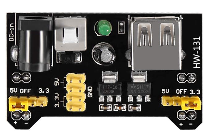
- ShillehTek MB102 Breadboard Power Supply Module - provides a stable 5V rail for the laser diode
- ShillehTek 6mm 650nm 5mW Red Laser Diode Module - the 5V laser module being switched
- ShillehTek 400-Point Solderless Breadboard - fast prototyping of the transistor switch circuit
- ShillehTek 120pcs 20cm Dupont Wires - makes the Pico W to breadboard connections easy
- ShillehTek 50cm Alligator Clips Test Leads - convenient temporary connections to the laser leads
- Raspberry Pi Pico 2W - the WiFi microcontroller board used in this build
External
- NPN transistor (for example 2N2222 or BC547) - acts as the switch for the 5V laser circuit
- 330-ohm resistor - limits current into the transistor base to protect the Pico W GPIO
- DC barrel power cord for the MB102 power supply module
- USB cable to power and program the Pico W
Note: The Pico W GPIO pins are 3.3V logic and should not be used to power a 5V laser module directly. Use a transistor switch and share a common ground between the Pico W and the 5V power supply.
Step-by-Step Guide
Step 1 - Set the MB102 to 5V and wire the transistor switch
Goal: Power the laser diode from a 5V rail and let the Pico W control it safely using an NPN transistor.
What to do: Configure the MB102 breadboard power supply for a 5V output using its onboard jumper. Use the 5V rail to power the laser diode, and use a transistor as a low-side switch controlled by Pico W GPIO 0.
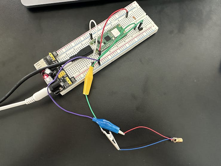
Wiring map:
Pico W GPIO Pin 0 ----> 330-ohm Resistor ----> Transistor Base (B)
MB102 GND --------------> Transistor Emitter (E)
MB102 5V ---------------> Laser Diode (+)
Laser Diode (-) --------> Transistor Collector (C)
Pico W GND -------------> MB102 GND
Connection details (same wiring, more explanation):
- Connect GPIO 0 to one side of the 330-ohm resistor, then connect the other side of the resistor to the transistor Base (B).
- Connect the transistor Emitter (E) to MB102 GND.
- Connect the laser diode (+) to MB102 5V.
- Connect the laser diode (-) to the transistor Collector (C).
- Connect Pico W GND to MB102 GND so both sides share a common ground.
Why use a transistor? The Pico W GPIO pins operate at 3.3V and can only source a limited current. A 5V laser diode needs a higher voltage supply, so the NPN transistor lets a low-current GPIO signal control the higher-power 5V circuit.
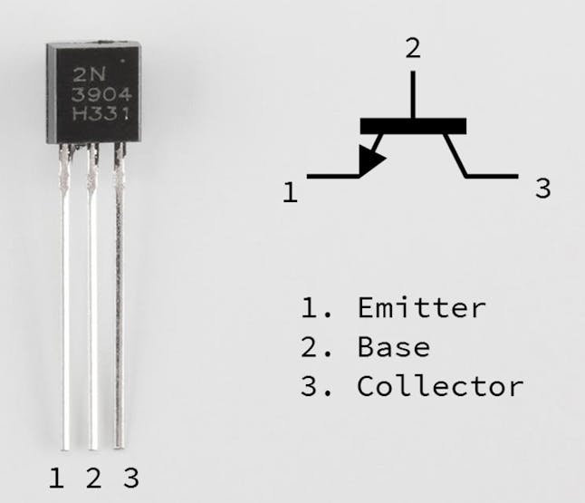
- Base (B): receives the Pico W control signal through the resistor
- Collector (C): connects to the laser diode negative terminal
- Emitter (E): connects to ground to complete the circuit
Why use a resistor? The 330-ohm resistor limits the current into the transistor base and helps protect the Pico W GPIO pin.

- It provides sufficient base current to saturate the transistor.
- It keeps the current demand on the GPIO pin well below its maximum limit (around 15 mA).
Expected result: The laser diode is powered from the MB102 5V rail, the Pico W is only connected to the transistor base through a 330-ohm resistor, and all grounds are shared.
Step 2 - Upload the MicroPython control script to the Pico W
Goal: Make the Pico W toggle GPIO 0 so the transistor turns the 5V laser diode on and off.
What to do: This assumes MicroPython is installed on your Pico W and you are using an editor like Thonny. Create a Python file (any name is fine) and upload it to the Pico W.
Code:
from machine import Pin
import time

# Initialize GPIO pin for the laser diode
laser = Pin(0, Pin.OUT)

# Function to blink the laser diode
while True:
    laser.value(1)  # Turn ON
    print("Laser ON")
    time.sleep(1)
    laser.value(0)  # Turn OFF
    print("Laser OFF")
    time.sleep(1)
Expected result: When the script runs, the Pico W repeatedly sets GPIO 0 high and low once per second.
Step 3 - Power up and test the circuit
Goal: Confirm the transistor switch is working and the laser is blinking reliably.
What to do: Power the Pico W via USB and power the MB102 so the breadboard rails supply 5V to the laser diode. Observe the laser diode blinking on and off every second.
Expected result: The laser diode turns on for one second, off for one second, repeating continuously. You can adjust the timing in the script as needed.
Conclusion
You built a simple and safe way to control a 5V laser diode using a Raspberry Pi Pico W by adding an NPN transistor and a 330-ohm base resistor, powered from an external 5V supply. This same approach works for many other higher-power loads that a microcontroller pin cannot drive directly.
Want the exact parts used in this build? Grab them from ShillehTek.com. If you want help customizing this project or building something similar for your product, check out our consulting: https://shillehtek.com/pages/iot-consulting.


.png?v=25000753014097803521779072085)

.png?v=68677308723310773341779072085)


