

Video Tutorial (Optional)
Watch first if you want to follow the full MPU6050 wiring and C++ setup on the Raspberry Pi Pico W in real time.
Project Overview
Raspberry Pi Pico W + MPU6050: In this project, you interface the MPU6050 accelerometer and gyroscope sensor with a Raspberry Pi Pico W using C++, then read accelerometer (g), gyroscope (dps), and temperature values over I2C and print them to serial.
If you are new to setting up the Raspberry Pi Pico W with the C++ SDK, refer to this previous guide: How to Write Your First C++ Script on the Raspberry Pi Pico W.
- Time: 30 to 60 minutes
- Skill level: Beginner to Intermediate
- What you will build: A Pico W C++ program that configures the MPU6050 and continuously prints IMU readings via USB serial
Parts List
From ShillehTek
- Raspberry Pi Pico 2 W + MPU6050 breadboard starter kit — Pico 2 W, MPU6050 module(s), breadboard, and jumper wires in one bundle (matches this I2C + C++ build with minimal shopping).
- Raspberry Pi Pico 2 W — Wi‑Fi Pico board used in this build (if you already have MPU6050, breadboard, and wires).
- MPU6050 (pre-soldered) IMU module — 6-axis accelerometer + gyro over I2C (if not using the starter kit).
- 400-point solderless breadboard — prototype I2C wiring without soldering (included in the starter kit).
- 120pcs 10 cm jumper wires — power, ground, SDA, and SCL between Pico and MPU6050 (included in the starter kit).
External
- CMake and a C++ development environment set up for Raspberry Pi Pico W
Step-by-Step Guide
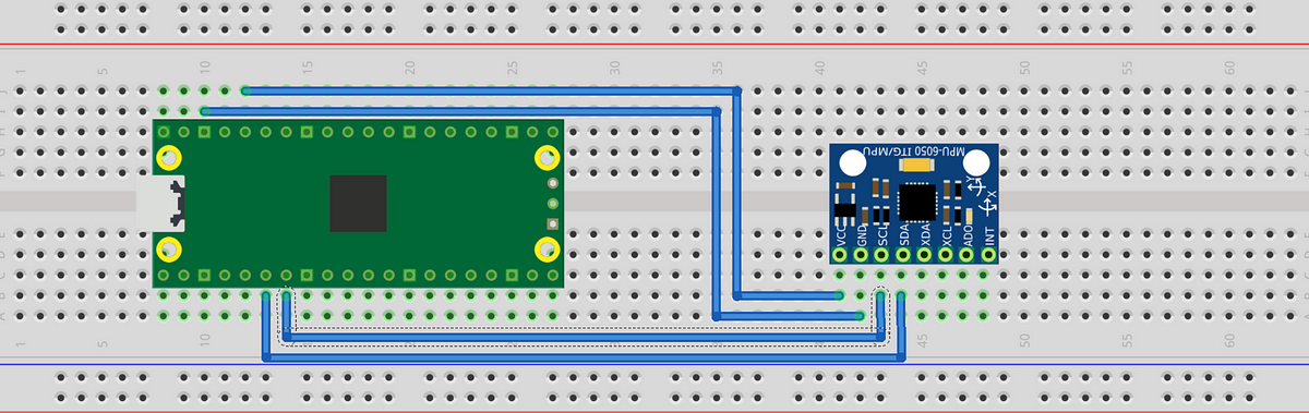
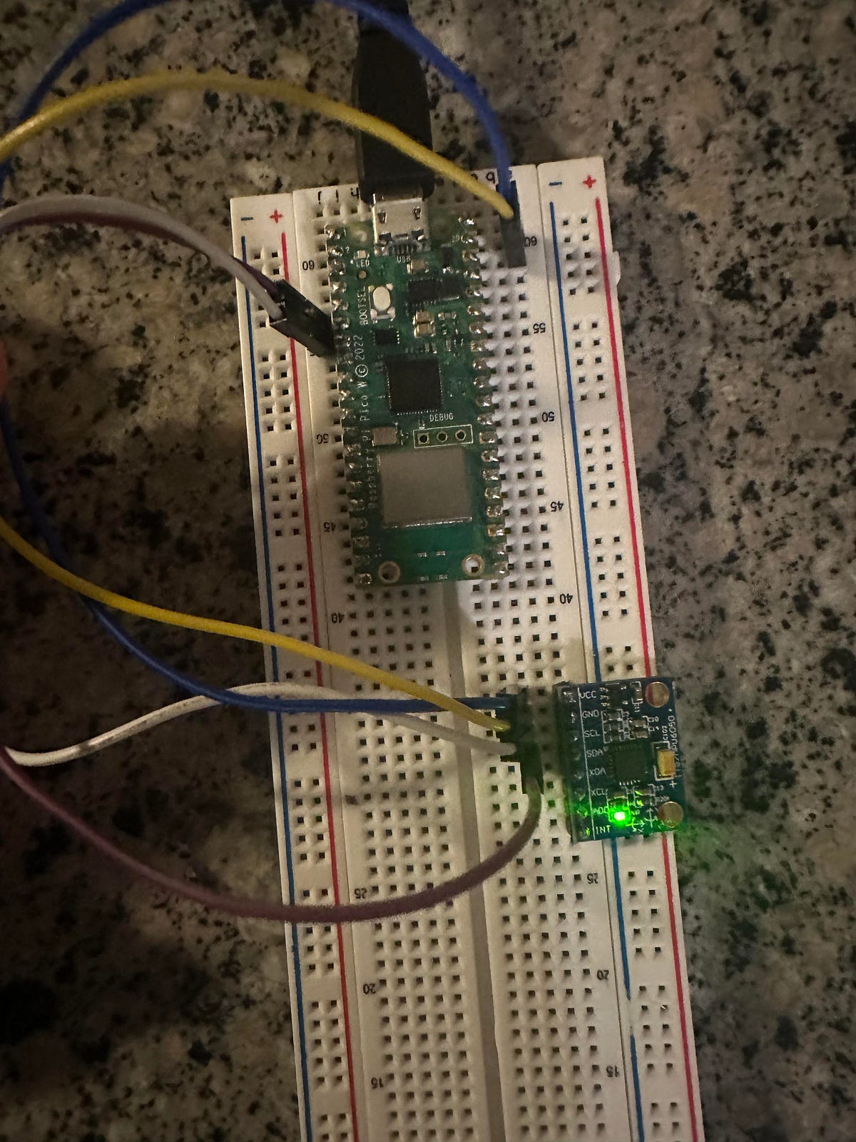
Step 1 - Wire the MPU6050 to the Pico W (I2C0)
Goal: Connect power and I2C lines so the Pico W can communicate with the MPU6050.
What to do: Make these four connections:
- VCC (MPU6050) to 3.3V (Pico W)
- GND (MPU6050) to GND (Pico W)
- SDA (MPU6050) to GPIO 4 (Pico W SDA for I2C0)
- SCL (MPU6050) to GPIO 5 (Pico W SCL for I2C0)
Expected result: The sensor is powered from 3.3V and connected to GPIO 4/5 for I2C communication.
Step 2 - Create the Pico C++ project and CMakeLists.txt
Goal: Configure the build so your program links against the Pico SDK, stdlib, and the hardware I2C library.
What to do: Create a project folder and add a CMakeLists.txt file with the following contents.
Code:
cmake_minimum_required(VERSION 3.13)

# Include the Pico SDK using the environment variable
include($ENV{PICO_SDK_PATH}/pico_sdk_init.cmake)

project(mpu6050_i2c_example)

# Initialize the Raspberry Pi Pico SDK
pico_sdk_init()

# Create an executable for the project
add_executable(mpu6050_i2c_example
    main.cpp
)

# Link the necessary libraries
target_link_libraries(mpu6050_i2c_example pico_stdlib hardware_i2c)

# Enable USB output
pico_enable_stdio_usb(mpu6050_i2c_example 1)
# Disable UART output
pico_enable_stdio_uart(mpu6050_i2c_example 0)

# Create map/bin/hex/uf2 files
pico_add_extra_outputs(mpu6050_i2c_example)
Expected result: Your project is set up to compile a main.cpp file and produce a UF2 for flashing.
Step 3 - Add the MPU6050 C++ code (main.cpp)
Goal: Initialize I2C on the Pico W, reset and configure the MPU6050, verify the device ID, then continuously read and print accelerometer, gyroscope, and temperature values.
What to do: Create a main.cpp file and paste in the code below.
Code:
#include "pico/stdlib.h"
#include "hardware/i2c.h"
#include <stdio.h>
// I2C defines
#define I2C_PORT i2c0
#define MPU6050_ADDR 0x68
// MPU6050 register addresses
#define REG_PWR_MGMT_1 0x6B
#define REG_ACCEL_XOUT_H 0x3B
#define REG_GYRO_CONFIG 0x1B
#define REG_ACCEL_CONFIG 0x1C
#define REG_SMPLRT_DIV 0x19
#define WHO_AM_I_REG 0x75
// Sensitivity scale factors for different ranges
#define ACCEL_SCALE_FACTOR_2G 16384.0 // for ±2g
#define ACCEL_SCALE_FACTOR_4G 8192.0 // for ±4g
#define ACCEL_SCALE_FACTOR_8G 4096.0 // for ±8g
#define ACCEL_SCALE_FACTOR_16G 2048.0 // for ±16g
#define GYRO_SCALE_FACTOR_250DPS 131.0 // for ±250 degrees per second
#define GYRO_SCALE_FACTOR_500DPS 65.5 // for ±500 degrees per second
#define GYRO_SCALE_FACTOR_1000DPS 32.8 // for ±1000 degrees per second
#define GYRO_SCALE_FACTOR_2000DPS 16.4 // for ±2000 degrees per second
// Select the desired scale factor
#define ACCEL_SCALE_FACTOR ACCEL_SCALE_FACTOR_4G // Change this to the desired accelerometer range
#define GYRO_SCALE_FACTOR GYRO_SCALE_FACTOR_250DPS // Change this to the desired gyroscope range
// Corresponding configuration values
#define ACCEL_CONFIG_VALUE 0x08 // for ±4g
#define GYRO_CONFIG_VALUE 0x00 // for ±250 degrees per second
#define SAMPLE_RATE_DIV 1 // Sample rate = 1kHz / (1 + 1) = 500Hz
void mpu6050_reset() {
uint8_t reset[] = {REG_PWR_MGMT_1, 0x80};
i2c_write_blocking(I2C_PORT, MPU6050_ADDR, reset, 2, false);
sleep_ms(200);
uint8_t wake[] = {REG_PWR_MGMT_1, 0x00};
i2c_write_blocking(I2C_PORT, MPU6050_ADDR, wake, 2, false);
sleep_ms(200);
}
void mpu6050_configure() {
// Set accelerometer range
uint8_t accel_config[] = {REG_ACCEL_CONFIG, ACCEL_CONFIG_VALUE};
i2c_write_blocking(I2C_PORT, MPU6050_ADDR, accel_config, 2, false);
// Set gyroscope range
uint8_t gyro_config[] = {REG_GYRO_CONFIG, GYRO_CONFIG_VALUE};
i2c_write_blocking(I2C_PORT, MPU6050_ADDR, gyro_config, 2, false);
// Set sample rate
uint8_t sample_rate[] = {REG_SMPLRT_DIV, SAMPLE_RATE_DIV};
i2c_write_blocking(I2C_PORT, MPU6050_ADDR, sample_rate, 2, false);
}
void mpu6050_read_raw(int16_t accel[3], int16_t gyro[3], int16_t *temp) {
uint8_t buffer[14];
uint8_t reg = REG_ACCEL_XOUT_H;
i2c_write_blocking(I2C_PORT, MPU6050_ADDR, ®, 1, true);
i2c_read_blocking(I2C_PORT, MPU6050_ADDR, buffer, 14, false);
accel[0] = (buffer[0] << 8) | buffer[1];
accel[1] = (buffer[2] << 8) | buffer[3];
accel[2] = (buffer[4] << 8) | buffer[5];
*temp = (buffer[6] << 8) | buffer[7];
gyro[0] = (buffer[8] << 8) | buffer[9];
gyro[1] = (buffer[10] << 8) | buffer[11];
gyro[2] = (buffer[12] << 8) | buffer[13];
}
int main() {
// Initialize chosen serial port
stdio_init_all();
// Initialize I2C
i2c_init(I2C_PORT, 400 * 1000);
gpio_set_function(4, GPIO_FUNC_I2C);
gpio_set_function(5, GPIO_FUNC_I2C);
gpio_pull_up(4);
gpio_pull_up(5);
// Reset and configure MPU6050
mpu6050_reset();
mpu6050_configure();
uint8_t who_am_i = 0;
uint8_t who_reg = WHO_AM_I_REG;
i2c_write_blocking(I2C_PORT, MPU6050_ADDR, &who_reg, 1, true);
i2c_read_blocking(I2C_PORT, MPU6050_ADDR, &who_am_i, 1, false);
printf("MPU6050 WHO_AM_I: 0x%02X\n", who_am_i);
if (who_am_i != 0x68) {
printf("MPU6050 not found!\n");
while (1);
}
int16_t accel[3], gyro[3], temp;
while (1) {
mpu6050_read_raw(accel, gyro, &temp);
// Convert raw accelerometer values to g
float accel_g[3];
accel_g[0] = accel[0] / ACCEL_SCALE_FACTOR;
accel_g[1] = accel[1] / ACCEL_SCALE_FACTOR;
accel_g[2] = accel[2] / ACCEL_SCALE_FACTOR;
// Convert raw gyroscope values to degrees per second
float gyro_dps[3];
gyro_dps[0] = gyro[0] / GYRO_SCALE_FACTOR;
gyro_dps[1] = gyro[1] / GYRO_SCALE_FACTOR;
gyro_dps[2] = gyro[2] / GYRO_SCALE_FACTOR;
// Print converted values
printf(
"aX = %.2f g | aY = %.2f g | aZ = %.2f g | gX = %.2f dps | gY = %.2f dps | gZ = %.2f dps | temp = %.2f°C\n",
accel_g[0], accel_g[1], accel_g[2],
gyro_dps[0], gyro_dps[1], gyro_dps[2],
temp / 340.00 + 36.53
);
sleep_ms(500);
}
return 0;
}
Expected result: On boot, the program prints the MPU6050 WHO_AM_I value (0x68 when detected), then continuously prints accelerometer (g), gyroscope (dps), and temperature readings.
Step 4 - Build, flash, and read the serial output
Goal: Compile the UF2, flash it to the Pico W, and confirm you can read live MPU6050 data.
What to do: Build your project using your normal Pico SDK workflow, then copy the generated UF2 to the Pico W (BOOTSEL mode). Open a serial monitor over USB to view the output.
Expected result: A repeating line of converted sensor values (aX/aY/aZ in g, gX/gY/gZ in dps, and temperature in °C) updates about every 500 ms.
Conclusion
You now have a working Raspberry Pi Pico W and MPU6050 setup in C++ that communicates over I2C, verifies the sensor using WHO_AM_I, and prints accelerometer, gyroscope, and temperature readings in real units.
Want the parts for this build? Grab breadboards, jumper wires, and more from ShillehTek.com. If you want help customizing this project for your application, you can hire expert IoT services on UpWork.


.png?v=25000753014097803521779072085)

.png?v=68677308723310773341779072085)


