

Project Overview
ESP8266 NodeMCU + 4-Channel Solid State Relay (SSR) Smart Plug: Build a 4-outlet, network-controlled AC switchboard that toggles each channel silently using UDP commands on your local WiFi.
- Time: 1 to 2 hours
- Skill level: Intermediate (mains voltage involved - read the safety note)
- What you will build: A NodeMCU-driven 4-channel SSR switchboard controlling lights or outlets, with simple UDP commands from your LAN.

Safety first: This build switches live AC. Enclose all mains wiring, never touch the circuit while energized, and if you are unsure, have someone qualified check your work.
Parts List
From ShillehTek
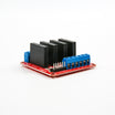
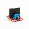
- 4-Channel 5V Solid State Relay Module - switches four AC loads silently (or the 1-Channel SSR for a single-outlet version)
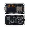
- ESP8266 NodeMCU Dev Board (with OLED) - provides WiFi + GPIO control (any ESP8266/ESP32 works)
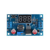
- LM2596 Adjustable Step-Down Converter with Voltmeter - dials in a stable 5V rail and lets you verify it on the display
- Dupont Jumper Wires - makes the GPIO-to-SSR wiring quick and clean
External
- A small AC-DC transformer/adapter to feed the converter
- Outlet(s) or lamp(s) to switch, mains cable, and an enclosure
Note: A solid-state relay is an electrically operated switch with no moving parts, built for AC loads. It switches silently at the zero crossing, never wears out mechanically, and needs only a logic-level signal to trigger.
Step-by-Step Guide
Step 1 - Relays vs. Solid State Relays
Goal: Know why SSRs fit this job.
What to do: A relay is an electrically operated switch; a solid-state relay is the same idea with zero moving parts, designed for alternating current. That means no coil clack, no contact arcing, and no mechanical wear, which is ideal for switching lights, gates, motorized devices, or anything plugged into the wall many times a day.
Expected result: You know when to reach for an SSR over a mechanical relay board.
Step 2 - Wire the 4-Channel Board
Goal: Connect power, logic, and the switched loads.
What to do: Feed your transformer into the step-down converter and connect its output to both the NodeMCU and the relay board VCC/GND. Wire relay inputs CH1 to CH4 to NodeMCU pins D1, D2, D5, and D6. On the output side, each SSR channel sits in series with the live wire of the outlet or lamp it controls, so the relay closes or breaks that circuit.

Expected result: Four independently switchable AC channels.
Step 3 - Set the 5V Rail
Goal: Protect your boards before first power-up.
What to do: Before connecting the NodeMCU, adjust the step-down converter to exactly 5V, which is what both the relay board and the NodeMCU VIN expect. Verify with a meter (or the converter onboard voltmeter) rather than trusting the potentiometer position.
Expected result: A verified 5V supply for logic and relays.
Step 4 - Flash the UDP Switch Firmware
Goal: Control the four channels over your network.
What to do: The sketch uses the ESP8266 WiFi and UDP libraries to connect to your network, listen on a UDP port, and toggle the four pins based on incoming commands. The full sketch lives in the author GitHub repository; the heart of it looks like this:
Code:
#include <ESP8266WiFi.h>
#include <WiFiUdp.h>

const char* ssid     = "Your_WIFI";
const char* password = "Your_Password";

WiFiUDP udp;
const int port = 4210;
char packet[16];

const int relayPins[4] = {D1, D2, D5, D6};
bool state[4] = {false, false, false, false};

void setup() {
  for (int i = 0; i < 4; i++) {
    pinMode(relayPins[i], OUTPUT);
    digitalWrite(relayPins[i], LOW);
  }
  WiFi.begin(ssid, password);
  while (WiFi.status() != WL_CONNECTED) delay(250);
  udp.begin(port);
}

void loop() {
  int size = udp.parsePacket();
  if (size) {
    int len = udp.read(packet, 15);
    packet[len] = 0;
    int ch = packet[0] - '1';          // command "1".."4" toggles a channel
    if (ch >= 0 && ch < 4) {
      state[ch] = !state[ch];
      digitalWrite(relayPins[ch], state[ch] ? HIGH : LOW);
    }
  }
}
Expected result: Sending a UDP packet ("1" through "4") toggles the matching outlet from any device on your LAN, such as a phone app, a terminal, or a home-automation server.
Step 5 - Box It and Put It to Work
Goal: Make it a safe, permanent smart plug.
What to do: Mount everything in an insulated enclosure with the mains side fully covered, label the four outputs, and integrate the UDP commands into whatever runs your home (scripts, Node-RED, or a phone shortcut). For a single lamp or gate, the 1-channel SSR version is the same build minus three channels.
Expected result: A silent, solid-state, WiFi-controlled power strip you built yourself.
Conclusion
This ESP8266 NodeMCU + 4-channel solid state relay build gives you silent AC switching on four outputs, controlled over WiFi with simple UDP packets. The same pattern can be reused for lighting, pumps, gates, and other mains-powered devices.
Reference credit: photos and the original guide are credited to Raka Amburo on Hackster.io.
Want the exact parts used in this build? Grab them from ShillehTek.com. If you want help customizing this project or building something for your product, check out our IoT consulting services.



.png?v=25000753014097803521791168436)

.png?v=68677308723310773341791168436)


