

Project Overview
ESP32-C6 Zigbee Light + Switch Network: Build a real two-node Zigbee network from scratch using two ESP32-C6 boards and the Arduino IDE built-in Zigbee examples, so one board acts as a smart light and the other acts as a wireless switch.
This is the same protocol behind millions of smart-home devices, running on a low-cost dev board.
- Time: ~1 hour
- Skill level: Intermediate
- What you will build: A working Zigbee on/off light and a paired Zigbee switch, which is a foundation for sensors, scene controllers, and full smart-home devices.

Parts List
From ShillehTek
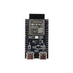
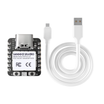
- ESP32-C6-N4 Pre-Soldered Development Board - you need two Zigbee-capable boards (one light, one switch); the Seeed XIAO ESP32-C6 works for either node
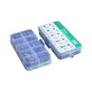
- Resistor Kit - for the LED's 220a9 current limiter
- 400-Point Breadboard - for quick prototyping
- Dupont Jumper Wires - to connect the LED and power rails
- Optional: Tactile Button Kit - if you want an external switch instead of the BOOT button
External
- An LED and two USB cables
Note: Zigbee runs on the 802.15.4 radio built into the ESP32-C6. The same chip also supports WiFi 6, BLE, and Thread. Zigbee's key advantage is mesh networking: every powered device can relay traffic, so networks can become more reliable as they grow.
Step-by-Step Guide
Step 1 - Set Up the IDE for Zigbee
Goal: Get the ESP32 core installed and select the correct Zigbee-capable board settings.
What to do: Install the latest ESP32 core via Boards Manager (add Espressif's board manager URL under File e2 86 92 Preferences if you have not already). Select your board under Tools e2 86 92 Board e2 86 92 ESP32 Arduino e2 86 92 ESP32C6 Dev Module (or your specific ESP32-C6 board).
The Zigbee examples ship with the ESP32 core, so no extra libraries are needed.
Expected result: The IDE shows File e2 86 92 Examples e2 86 92 Zigbee.
Step 2 - Wire and Flash the Light Node
Goal: Create a Zigbee on/off light end device that drives an LED.
What to do: Wire GPIO4 e2 86 92 220a9 resistor e2 86 92 LED e2 86 92 GND. Open File e2 86 92 Examples e2 86 92 Zigbee e2 86 92 Zigbee_On_Off_Light.
Set two Tools options:
- Zigbee mode: Zigbee ED (end device)
- Partition Scheme: Zigbee 4MB with spiffs
The sketch registers the LED as a light endpoint:
#ifndef ZIGBEE_MODE_ED
#error "Zigbee end device mode is not selected in Tools->Zigbee mode"
#endif

#include "Zigbee.h"

#define ZIGBEE_LIGHT_ENDPOINT 10
uint8_t led = 4;                 // LED on GPIO4
uint8_t button = BOOT_PIN;       // hold to factory-reset the node

ZigbeeLight zbLight = ZigbeeLight(ZIGBEE_LIGHT_ENDPOINT);

void setLED(bool value) {
  digitalWrite(led, value);
}

void setup() {
  Serial.begin(115200);
  pinMode(led, OUTPUT);
  pinMode(button, INPUT_PULLUP);

  zbLight.onLightChange(setLED);   // Zigbee commands drive the LED
  Zigbee.addEndpoint(&zbLight);
  Zigbee.begin();                  // join the network
}
Expected result: The light node boots and searches for a Zigbee network to join.
Step 3 - Flash the Switch Node (the Coordinator)
Goal: Create the Zigbee network and send on/off commands to the light.
What to do: On the second board, open File e2 86 92 Examples e2 86 92 Zigbee e2 86 92 Zigbee_On_Off_Switch.
Use these Tools options on the switch node:
- Zigbee mode: Zigbee ZCZR (coordinator/router)
- Partition Scheme: Zigbee 4MB with spiffs
The coordinator forms the network that the light joins, and its BOOT button becomes the toggle:
#ifndef ZIGBEE_MODE_ZCZR
#error "Zigbee coordinator mode is not selected in Tools->Zigbee mode"
#endif

#include "Zigbee.h"

#define SWITCH_ENDPOINT_NUMBER 5
#define GPIO_INPUT_IO_TOGGLE_SWITCH BOOT_PIN  // or an external button

ZigbeeSwitch zbSwitch = ZigbeeSwitch(SWITCH_ENDPOINT_NUMBER);

void setup() {
  Serial.begin(115200);
  Zigbee.addEndpoint(&zbSwitch);
  Zigbee.begin(ZIGBEE_COORDINATOR);   // form the network
  // button handling binds presses to on/off commands
  // sent to the paired light endpoint
}
Expected result: The coordinator forms a network; the light node joins it automatically.
Step 4 - Pair and Test
Goal: Toggle an LED wirelessly using Zigbee, with no WiFi involved.
What to do: Power both boards and watch the serial monitors. The coordinator opens the network, the light joins, and the switch binds to the light's endpoint.
Press the switch board's BOOT button. The LED on the other board should toggle. This is a Zigbee command traveling over 802.15.4, similar to how a store-bought bulb and remote work.

Expected result: Wireless on/off control between your two ESP32-C6 nodes.
Step 5 - Common Pairing Checks and Extensions
Goal: Confirm the setup if pairing fails, then understand how to expand the project.
What to do: If the nodes will not pair, confirm both radios initialized (check serial output), keep them in range, and make sure both use the same channel. Compile errors usually mean an outdated ESP32 core or the wrong Zigbee mode or partition scheme selected.
From here you can join the light to Home Assistant, SmartThings, or Alexa through a Zigbee gateway, add more lights and switches for a whole-room system, or swap the LED for a relay to switch real lamps.
Expected result: A working two-node network and a clear path to a larger Zigbee smart-home build.
Conclusion
You built a complete Zigbee network with two ESP32-C6 boards: a coordinator that forms the network, an end device that joins it, and real on/off commands that toggle an LED across the room.
This same endpoint-based pattern is what you will use for Zigbee sensors, scene controllers, and gateway-connected smart-home devices.
Want the exact parts used in this build? Grab them from ShillehTek.com. If you want help customizing this project or building something for your product, check out our IoT consulting services.
Credits: Photos and images are credited to tech_nickk on Hackster.io. This ShillehTek version references that original guide and the Zigbee example code by Espressif Systems and Jan Proche1zka.





.png?v=25000753014097803521791168436)

.png?v=68677308723310773341791168436)


