Controlling a 5V Laser Diode with Raspberry Pi Pico W

Laser diodes are fascinating components that bring a spark of creativity to countless DIY projects. From precision alignment tools to interactive laser pointer games for pets, laser diodes have captured the imagination of makers and tinkerers worldwide. In this tutorial, we'll explore how to connect a 5V laser diode to the Raspberry Pi Pico W and control it using GPIO pins.
The Raspberry Pi Pico W, with its compact size and wireless capabilities, is a perfect platform for experimenting with hardware like laser diodes. Since the Pico W operates at 3.3V logic and the laser diode requires a 5V supply, we'll be using a simple transistor circuit to act as a switch, enabling us to control the diode from the Pico W's GPIO pins safely and effectively. To power the laser diode, we'll use the popular MB102 breadboard power supply, which can provide a stable 5V source.
In this guide, you'll learn:
  • How to set up the MB102 breadboard power supply for powering the laser diode.
  • How to build a transistor-based circuit to control the laser diode using the Pico W's GPIO pins.
  • How to write MicroPython code to turn the laser diode on and off.
By the end of this tutorial, you'll not only have a functional setup but also the knowledge to use laser diodes in creative projects like line-following robots, DIY laser tripwires, or even simple laser shows. Let’s get started!
— — -
Before we delve into the topic, we invite you to support our ongoing efforts and explore our various platforms dedicated to enhancing your IoT projects:
  • Subscribe to our YouTube Channel: Stay updated with our latest tutorials and project insights by subscribing to our channel at YouTube — Shilleh.
  • Support Us: Your support is invaluable. Consider buying me a coffee at Buy Me A Coffee to help us continue creating quality content.
  • Hire Expert IoT Services: For personalized assistance with your IoT projects, hire me on UpWork.
ShillehTek Website (Exclusive Discounts):
ShillehTekAmazon Store:
— — -
Components Overview
  • Raspberry Pi Pico W: A compact microcontroller with GPIO pins for controlling external devices and built-in Wi-Fi capabilities for IoT projects. In this project, it serves as the control unit for toggling the laser diode. Make sure you have a cable to power the Pico W.
  • ShillehTekMB102 Power Supply Module: A breadboard-compatible power module that provides stable 5V and 3.3V outputs, ideal for powering components like the 5V laser diode safely and reliably. You will need a DC cord to power the MB102.
  • ShillehTek5V Laser Diode: A small, focused-beam laser module commonly used in alignment systems, pointers, and various DIY electronics projects. It will be powered at 5V and controlled via the Pico W.
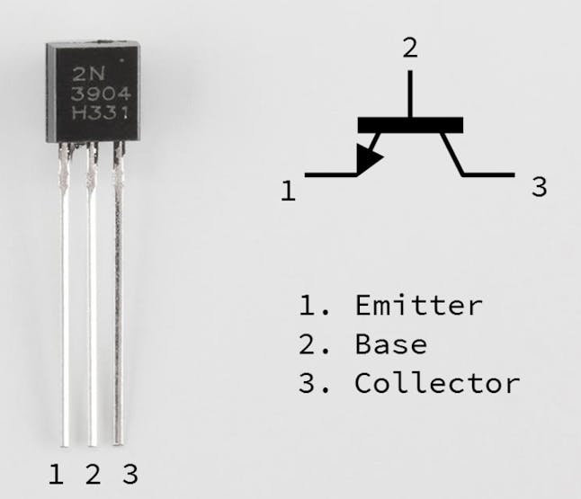
  • NPN Transistor (e.g., 2N2222 or BC547): A versatile electronic switch that allows the Pico W to control the 5V laser diode safely, ensuring the GPIO pin's 3.3V output is sufficient for operation.
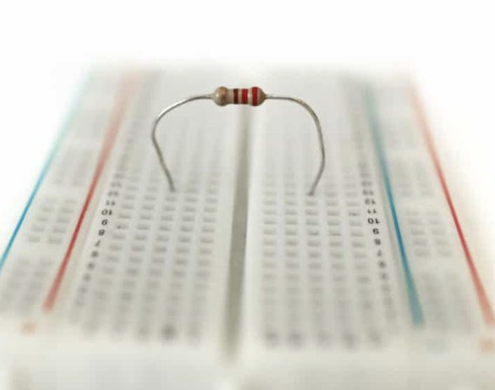
  • 330-Ohm Resistor: Used to limit the current flowing to the transistor’s base, protecting the GPIO pin on the Pico W from overcurrent damage.
  • ShillehTekBreadboard and Jumper Wires: Essential for assembling a temporary and flexible prototype circuit, allowing for easy connections and adjustments during testing.
  • Alligator Jumper Wires: Convenient for connecting directly to the laser diode’s leads, providing a secure and temporary connection for quick prototyping.
Step 1: Circuit Connections
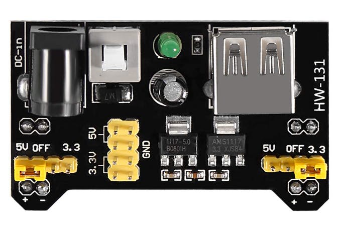
Before assembling the circuit on the breadboard, ensure that the MB102 power supply module is set up correctly. The MB102 provides both 3.3V and 5V outputs, and for this project, we need to configure it to supply 5V to power the laser diode. If we power the laser with 3.3V from the Pico W, you will realize it is quite weak, so the MB102 module will allow us to get it to the needed 5V.
Make sure the MB102 power supply is set to 5V by checking the onboard jumper. Adjust the jumper to the 5V position if necessary. We can use the left side as shown below to power the rails of the breadboard with 5V.
Next we should begin to make our connections on the breadboard as follows:
Pico W GPIO Pin 0 ----> 330-ohm Resistor ----> Transistor Base (B) MB102 GND --------------> Transistor Emitter (E) MB102 5V ---------------> Laser Diode (+) Laser Diode (-) --------> Transistor Collector (C) Pico W GND -------------> MB102 GND
To control the 5V laser diode using the 3.3V GPIO pin of the Raspberry Pi Pico W, we use a transistor as an electronic switch. Here's a bit more detail on the connections to help you not get confused.
Connect the GPIO Pin to the Transistor Base via a Resistor:
  • Connect GPIO Pin 0 of the Pico W to one end of a 330-ohm resistor.
  • Connect the other end of the resistor to the Base (B) of the NPN transistor.This resistor limits the current flowing into the base of the transistor, protecting the GPIO pin from excessive current.
Connect the Transistor Emitter to Ground:
  • Connect the Emitter (E) of the transistor to the GND pin of the MB102 power supply module.This completes the ground circuit for the transistor.
Connect the Laser Diode to the Power Supply and Transistor:
  • Connect the positive terminal (+) of the laser diode to the 5V output of the MB102 power supply module.
  • Connect the negative terminal (-) of the laser diode to the Collector (C) of the transistor.The transistor acts as a switch, allowing the laser diode to be powered only when the GPIO pin sends a signal.
Connect the Ground of the Pico W to the MB102 Ground:
  • Connect the GND pin of the Pico W to the GND of the MB102 power supply module.This ensures a common ground between the microcontroller and the external power source.
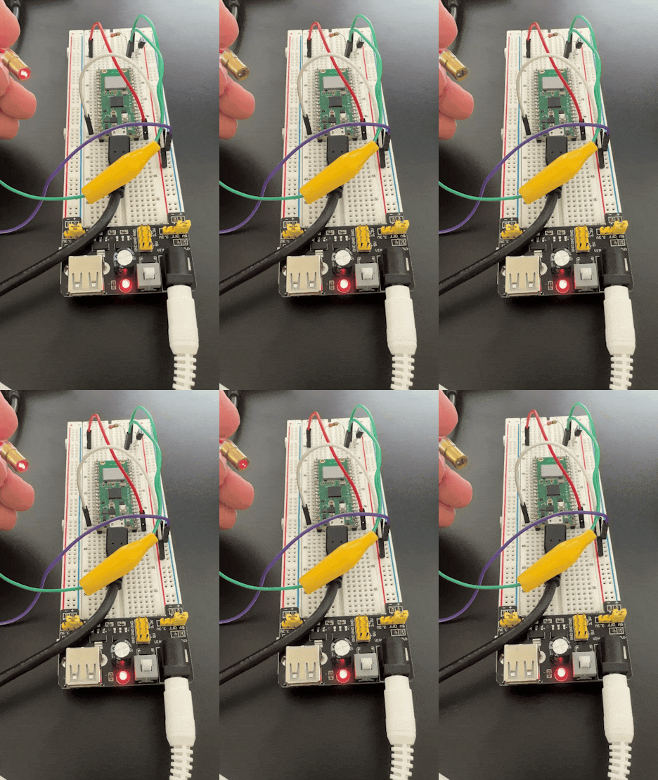
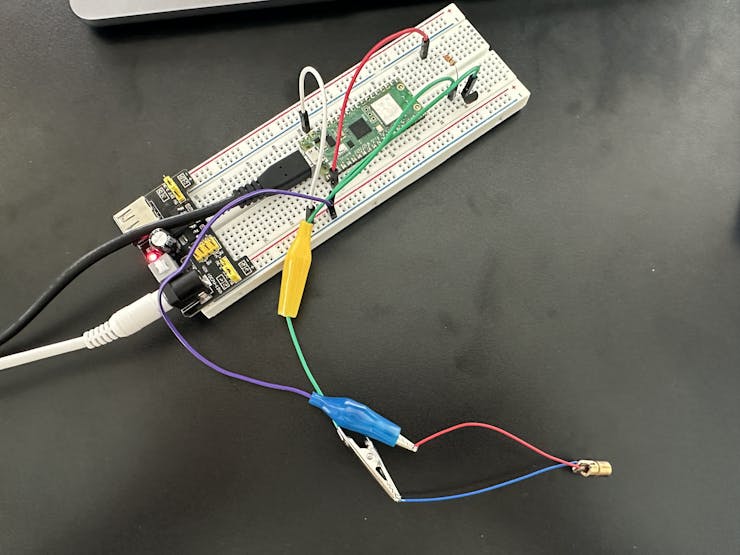
Here is how the circuit should look in real life.
----
Why Use a Transistor?
The Raspberry Pi Pico W GPIO pins operate at 3.3V and can only source a limited amount of current, typically insufficient to directly power a 5V laser diode. The NPN transistor acts as a bridge, allowing a low-current 3.3V signal from the GPIO pin to control the higher-current 5V circuit powering the laser diode.
  • Transistor Base (B): Receives the low-voltage signal from the Pico W GPIO pin.
  • Transistor Collector (C): Connects to the laser diode’s negative terminal, controlling its current flow.
  • Transistor Emitter (E): Connects to ground, completing the circuit.
----
Why Use a Resistor?
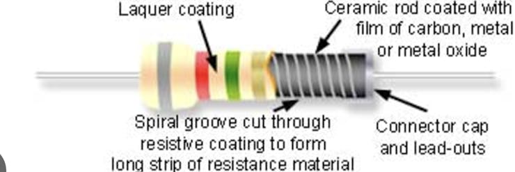
A resistor is typically made from a thin film of conductive material like carbon, metal, or metal oxide, deposited on an insulating substrate, essentially creating a resistive element that limits the flow of electric current in a circuit; common types include carbon composition, metal film, and metal oxide film resistors, with some high-power resistors being made from wound metal wire on a ceramic core.
The 330-ohm resistor is important for protecting the GPIO pin. Without it, too much current could flow into the transistor’s base, potentially damaging the Pico W.
Using 330 ohms strikes a good balance for this project:
  • It provides sufficient base current to saturate the transistor.
  • It keeps the current demand on the GPIO pin well below its maximum limit (around 15 mA).
If you use a higher resistor value (e.g., 1 kΩ), the base current may not be enough to fully saturate the transistor, leading to inefficient switching. A lower value (e.g., 100 ohms) might draw excessive current from the GPIO pin, risking damage.
-----
Step 2: Program the Pico W
This tutorial assumes you have MicroPython already installed onto your device and you have the Thonny editor.
  • Use the following Python script to control the laser diode:
from machine import Pin import time # Initialize GPIO pin for the laser diode laser = Pin(0, Pin.OUT) # Function to blink the laser diode while True: laser.value(1) # Turn ON print("Laser ON") time.sleep(1) laser.value(0) # Turn OFF print("Laser OFF") time.sleep(1)
  • Upload the code to the Pico W using an editor like Thonny. Name the Python file whatever you like.
Step 3: Test Your Circuit
  • Power on the Pico W via USB and observe the laser diode blinking on and off every second. You can adjust this very simple script as need be.
Conclusion
This project demonstrated how to control a 5V laser diode using the Raspberry Pi Pico W, a transistor, and an external power supply. By using a transistor, we can safely interface components requiring higher power than the microcontroller can handle directly. This method is not limited to laser diodes; you can extend it to control other devices like motors, relays, or high-power LEDs.
This hands-on exercise provides a foundation for more advanced projects involving external devices and GPIO control, making it a great starting point for electronics enthusiasts and IoT developers.

Create a free account to access full content.

All access to code and resources on ShillehTek.

Signup Now

Already a member? Sign In

Explore More on Our Blog

Controlling a 5V Laser Diode with Raspberry Pi Pico W

Controlling a 5V Laser Diode with Raspberry Pi Pico W

Learn how to safely control high-power components like a 5V laser diode using the Raspberry Pi Pico W and a...

How to Connect and Use the HCSR501 PIR Sensor with a Raspberry Pi Pico/Pico W

How to Connect and Use the HCSR501 PIR Sensor with a Raspberry Pi Pico/Pico W

Learn how to set up the HCSR501 PIR sensor with a Raspberry Pi Pico to detect motion and trigger...

Powering the Raspberry Pi Pico W with the MB102 Power Supply

Powering the Raspberry Pi Pico W with the MB102 Power Supply

Learn how to power your Raspberry Pi Pico W projects easily and flexibly with the MB102 Power Supply Module...

How to Use L298N Motor Driver with Pico W

How to Use L298N Motor Driver with Pico W

Learn how to use the L298N motor driver to control DC motors with the Raspberry Pi Pico W in MicroPython.

Controlling an LED with a Snap Using the KY-037 Sound Sensor and Raspberry Pi

Controlling an LED with a Snap Using the KY-037 Sound Sensor and Raspberry Pi

Discover how to set up, code, and activate the LED based on detected sound with the Raspberry Pi...

Getting Started with the KY-037 Sound Sensor and Raspberry Pi: Detecting Sound Using Python

Getting Started with the KY-037 Sound Sensor and Raspberry Pi: Detecting Sound Using Python

In this tutorial, I’ll guide you through setting up the KY-037 sound sensor with a Raspberry Pi using...

How to Post to Reddit Using Python

How to Post to Reddit Using Python

Post to reddit automatically using a Python script.

How to Create a Time-Lapse Video with a Raspberry Pi Camera

How to Create a Time-Lapse Video with a Raspberry Pi Camera

Learn how to make a timelapse with your Raspberry Pi in Python.

How to Integrate the MPU6050 with the STM32 Blue Pill

How to Integrate the MPU6050 with the STM32 Blue Pill

Learn how to measure acceleration with the STM32 and the MPU6050 in the Arduino IDE.

Getting Started with STM32 Blue Pill in Arduino IDE Using a USB to TTL Converter — Write Your First Program

Getting Started with STM32 Blue Pill in Arduino IDE Using a USB to TTL Converter — Write Your First Program

This comprehensive tutorial will guide you through the process of setting up and programming the STM32 Blue Pill...

Back to blog

Leave a comment

Please note, comments need to be approved before they are published.