

Project Overview
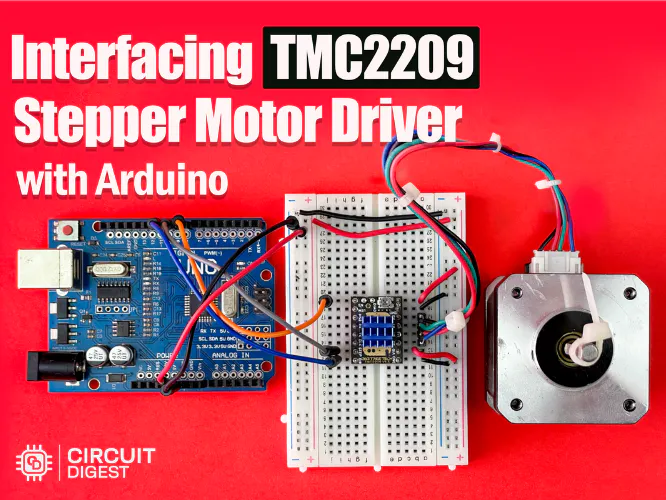
Arduino UNO + TMC2209 stepper driver: In this build you wire a TMC2209 silent stepper driver to an Arduino UNO and run a NEMA 17 stepper motor using three control pins (STEP, DIR, EN) for smooth, quiet motion without needing UART setup.
The TMC2209 is popular because StealthChop smooths coil current for near-silent operation. You can start with basic STEP/DIR control today, then add optional UART features later if you want runtime current tuning or diagnostics.
- Time: 30-45 minutes
- Skill level: Beginner
- What you will build: A NEMA 17 stepper running back and forth under Arduino control through a TMC2209 driver, with no UART configuration required.
Parts List
From ShillehTek
- MKS TMC2209 Motor Driver with Heatsink - TMC2209 module with heatsink for quiet STEP/DIR control with the wiring in this guide.
- Arduino Nano V3 (pre-soldered) - a drop-in alternative to the Uno if you want a smaller board (the wiring is identical for D8 / D9 / D10).
- A4988 Pre-Soldered Stepper Motor Driver - same pinout as the TMC2209 if you want a louder but cheaper alternative for testing.
- 28BYJ-48 Stepper + ULN2003 Driver Kit - if you want to learn stepper control on a 5 V motor before you scale up to NEMA 17.
- 120pcs 20cm Dupont Jumper Wires - for STEP / DIR / EN signal wiring.
- 400-Point Solderless Breadboard - tidy way to share grounds between the Arduino and the driver.
- LM2596 Step-Down Buck Converter - useful if you only have a 24 V supply but need 12 V for VM, or if you want a clean 5 V logic rail.
External
- Arduino Uno board (or any 5 V Arduino-compatible).
- NEMA 17 bipolar stepper motor (1.7 A or lower).
- 12-24 V external power supply for the motor (VM).
- USB cable for programming the Arduino.
- Small flat-blade screwdriver for the VREF trim pot.
Note: Set the VREF trim pot on the TMC2209 to roughly 60-70% of your motor’s rated phase current before you power up. Driving a stepper too hot is the fastest way to roast a motor or trip the driver into thermal shutdown.
Step-by-Step Guide
Step 1 - Understand the control pins
Goal: Know what the Arduino is actually controlling so the wiring and code make sense.
What to do: You will use three Arduino digital pins:
- D8 (EN): pulled LOW to enable the driver, HIGH to free the motor.
- D9 (STEP): a rising edge advances the rotor by one micro-step.
- D10 (DIR): sets rotation direction - HIGH one way, LOW the other.
Expected result: You have a clear plan for which wires go where, and what behavior to expect from the sketch.
Step 2 - Set the driver current (VREF)
Goal: Tell the TMC2209 how much phase current it is allowed to push into your motor.
What to do: Power the driver from a bench supply (no STEP pulses yet), put a multimeter between VREF and GND, and turn the trim pot until you read about 0.7 × I_rms for your motor (often around 0.6-0.9 V for typical NEMA 17s).
Expected result: The driver runs cool to the touch under load. If you cannot hold a finger on it, drop VREF further.
Step 3 - Wire the logic side (Arduino to TMC2209)
Goal: Connect EN, STEP, and DIR to the Arduino, plus VIO to 5 V and a shared ground.
What to do: Make these connections:
| TMC2209 Pin | Arduino / Power | Notes |
|---|---|---|
| EN | D8 | LOW = driver enabled, HIGH = coast |
| STEP | D9 | One step per rising edge |
| DIR | D10 | HIGH or LOW selects direction |
| VIO | Arduino 5 V | Logic-side power so 5 V signals are recognized |
| GND | Arduino GND | Must be shared with the driver and motor PSU ground |
Tip: Tie every ground together (Arduino GND, driver GND, and motor PSU GND). A floating ground is a common reason new builds “mostly work” with random missed steps.
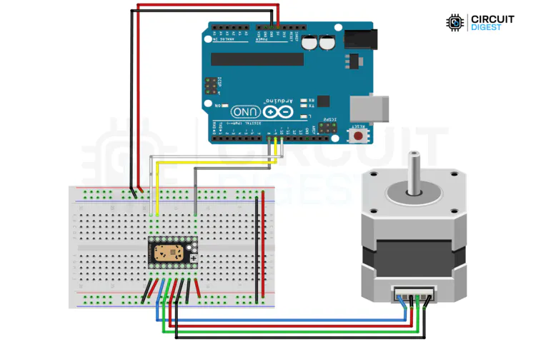
Step 4 - Wire the motor side (power and coils)
Goal: Connect the NEMA 17 coils to the driver and provide VM motor power safely.
What to do: Match the two coils on your stepper to the 1A/1B and 2A/2B pads on the driver (check the motor datasheet so you do not cross phases). Wire the 12-24 V supply to VM/VS and tie its ground to the same GND rail as the Arduino.
| TMC2209 Pin | Arduino / Power | Notes |
|---|---|---|
| VM / VS | External 12-24 V supply | Motor power - size to your motor’s rated voltage |
| GND | Common ground | Arduino GND + driver GND + motor PSU GND must all meet |
| 2A / 2B / 1A / 1B | NEMA 17 coils | Two coils, two wires each - pair them by datasheet |

Step 5 - Upload the Arduino sketch
Goal: Run a minimal STEP/DIR program so the motor sweeps forward and reverse.
What to do: Open the Arduino IDE, paste the sketch below into a new project, select the correct board and port, then upload.
Code:
// Pin Definitions
#define EN_PIN   8   // LOW: driver enabled, HIGH: driver disabled
#define STEP_PIN 9   // One step on each rising edge
#define DIR_PIN  10  // Selects rotation direction

int noOfSteps         = 500;   // Steps per direction
int microSecondsDelay = 1000;  // Delay between STEP edges

void setup() {
  pinMode(EN_PIN,   OUTPUT);
  pinMode(STEP_PIN, OUTPUT);
  pinMode(DIR_PIN,  OUTPUT);

  digitalWrite(EN_PIN,  LOW);   // Enable the driver
  digitalWrite(DIR_PIN, LOW);   // Initial direction
}

void loop() {
  // Forward
  digitalWrite(DIR_PIN, LOW);
  moveSteps(noOfSteps);

  // Reverse
  digitalWrite(DIR_PIN, HIGH);
  moveSteps(noOfSteps);

  delay(500);                   // Pause between sweeps
}

void moveSteps(int steps) {
  for (int i = 0; i < steps; i++) {
    digitalWrite(STEP_PIN, HIGH);
    delayMicroseconds(microSecondsDelay);
    digitalWrite(STEP_PIN, LOW);
    delayMicroseconds(microSecondsDelay);
  }
}
Expected result: After upload, the NEMA 17 begins sweeping smoothly back and forth. If the motor jitters or skips, VREF may be too low or a coil pair may be swapped.
Conclusion
You just built a quiet stepper setup using an Arduino UNO, a TMC2209 driver, and a NEMA 17 motor, controlled with simple STEP/DIR/EN signals. Once it is moving reliably, the main next steps are mechanical mounting and fine-tuning VREF for your motor and workload.
Want the exact parts used in this build? Grab them from ShillehTek.com. If you want help customizing this for a multi-axis machine (driver selection, current tuning, or firmware planning), check out our IoT consulting services.
Image credits: Photos and diagrams are credited to Electroscope Archive on Hackster.io.


.png?v=25000753014097803521779072085)

.png?v=68677308723310773341779072085)


