

Project Overview
Arduino Uno + LDR (photoresistor) automatic night light: You will read a photoresistor on an Arduino analog pin, calibrate a light threshold, and switch an LED (or a relay-controlled lamp) on in the dark and off in daylight.
A photoresistor changes resistance with light. Put it in a voltage divider and the Arduino can measure brightness as a changing voltage. With one threshold (plus hysteresis to prevent flicker), you can build the same style of automatic light control used in streetlights, garden lights, and screens.
- Time: ~30 minutes
- Skill level: Beginner
- What you will build: A light-sensing circuit that turns an LED on in the dark and off in daylight, with live readings for calibration.

Parts List
From ShillehTek
- Arduino Uno R3 Super Starter Kit - includes the photoresistor, LEDs, and resistors
- Resistor Kit - 10kΩ for the divider, 220Ω for the LED
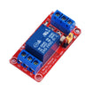
- 1-Channel 5V Relay Module - to switch a real lamp instead of an LED
- 400-Point Breadboard - for quick prototyping
- Dupont Jumper Wires - for breadboard wiring
External
- None for the basic build
Note: An LDR cannot be read directly; it needs a voltage divider. LDR from 5V to A0, 10kΩ from A0 to ground. In this wiring: bright light = high reading, darkness = low reading.
Step-by-Step Guide
Step 1 - Wire the Divider and LED
Goal: Turn resistance into a readable voltage.
What to do: Connect one LDR leg to 5V. Connect the other LDR leg to A0 and also to a 10kΩ resistor that goes to GND (that junction is your divider output). Wire an LED on D2 through a 220Ω resistor to GND.

Expected result: A0 now sees a voltage that tracks room brightness.
Step 2 - Read and Calibrate
Goal: Find your threshold for your room and sensor.
What to do: Print analogRead(A0) to Serial every 200 ms and watch the numbers. Note the value in normal light, then cup your hand over the sensor and note the dark value. Set your threshold about halfway between the two readings. Every room (and every LDR) is different, so measure instead of guessing.
Expected result: Two readings (bright and dark) and a threshold value between them.
Step 3 - The Night Light Sketch
Goal: Dark = on, bright = off.
Code:
const int LDR = A0;
const int LED = 2;
const int THRESHOLD = 500;    // from your Step 2 calibration
const int HYSTERESIS = 40;    // no flicker at the boundary

void setup() {
  Serial.begin(9600);
  pinMode(LED, OUTPUT);
}

void loop() {
  int light = analogRead(LDR);   // 0 (dark) .. 1023 (bright)
  Serial.println(light);

  if (light < THRESHOLD - HYSTERESIS)      digitalWrite(LED, HIGH); // dark
  else if (light > THRESHOLD + HYSTERESIS) digitalWrite(LED, LOW);  // bright

  delay(200);
}
What to do: Upload the sketch, then dim the lights and watch the LED. The hysteresis band keeps the LED from flickering when the reading hovers near the threshold.
Expected result: The LED turns on when it is dark and turns off when it is bright, while Serial Monitor shows the live sensor readings.
Step 4 - Switch Something Real
Goal: Move from an LED demo to an actual night light.
What to do: Move the output pin to the relay module signal input and wire a lamp through the relay contacts so the same threshold logic controls a real light. Dusk will turn on the lamp and daylight will turn it off.
Expected result: Automatic lighting controlled by the Arduino and the LDR sensor.
Conclusion
You built an Arduino Uno light sensor project using an LDR and a voltage divider, then calibrated real readings to choose a threshold. With simple threshold logic and hysteresis, your circuit can switch an LED (or a relay-driven lamp) on in the dark and off in daylight.
Want the exact parts used in this build? Grab them from ShillehTek.com. If you want help customizing this project or building something for your product, check out our IoT consulting services.
Credits
All photos and images in this tutorial are credited to Lucas Fernando on Hackster.io. The original guide by Lucas Fernando served as the reference for this ShillehTek version. We thank him for the excellent work in the maker community.






.png?v=25000753014097803521791168436)

.png?v=68677308723310773341791168436)


