

Project Overview
Arduino rain sensor module: In this guide you use an Arduino (Nano or any compatible board) with a raindrop sensor module to detect surface water and classify conditions as Not Raining, Rain Warning, or Flood on the Serial Monitor.
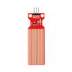
A rain sensor (often called a raindrops module) detects actual water on a surface, which a humidity sensor cannot do. The sensing board is a grid of printed traces that acts like a variable resistor: around 2 MΩ when bone-dry, dropping to roughly 100 kΩ when wet. The wetter the board, the more current flows.
- Time: 30 minutes
- Skill level: Beginner
- What you will build: A rain detector that classifies dry, drizzle, and downpour on the Serial Monitor.

Parts List
From ShillehTek
- Rain and Water Level Detection Sensor Module - includes the detection plate and the comparator board with A0 and D0 outputs
- Arduino Nano V3 - reads the analog signal and prints the rain state (any Arduino board works)
- 120pcs 20cm Dupont Jumper Wires - for module power, analog signal, and the sensor plate loop connection
External
- A little water for testing
Note: The module has two outputs: A0 (analog level) and D0 (digital threshold with onboard LED). This guide uses the analog output (A0) for graded detection.
Step-by-Step Guide
Step 1 - Get to Know the Module
Goal: Identify the pins and what each one does before wiring.
What to do: The comparator board exposes four pins: A0 (analog out), D0 (digital out), GND, and VCC. It also has two loop pins (+/-) that connect to the separate sensing board. The detection board itself is about 5.5 x 4.0 cm and works by letting water bridge its printed leads.
What to do: For analog use, power the module from 5V. If you only use the digital output (D0), 3.3V is typically fine.

Expected result: You can identify A0, D0, GND, VCC, and the two hookups for the sensor board.
Step 2 - Bench-Test It First
Goal: Confirm the sensor and comparator board are working before uploading code.
What to do: Power the module (VCC to 5V, GND to GND) and drip a few water droplets on the detection board. The D0 LED should light.
What to do: If it does not light, recheck the hookup, try slightly salty water (very pure water conducts poorly), and inspect solder joints on the small SMD parts (a known weak point on some batches). If none of that helps, the unit may be defective.

Expected result: The D0 LED responds when you add water to the sensing board.
Step 3 - Wire It to the Arduino
Goal: Connect the analog output so the Arduino can read rain intensity.
What to do: Make these five connections:
Module VCC -> Arduino 5V
Module GND -> Arduino GND
Module A0  -> Arduino A0
Module (+) -> sensing board (+)
Module (-) -> sensing board (-)
Expected result: The sensing board is connected through the comparator board to the Arduino, with A0 feeding Arduino A0.
Step 4 - Upload the Three-State Sketch
Goal: Read the analog value (0 to 1023) and label it as Not Raining, Rain Warning, or Flood.
What to do: Upload the sketch below (after Reichenstein7's example). It reads analog A0 and maps the sensor range into three zones: soaked board prints Flood, droplets print Rain Warning, and dry prints Not Raining.
// Rain sensor three-state example (after Reichenstein7)
const int sensorMin = 0;     // sensor minimum
const int sensorMax = 1024;  // sensor maximum

void setup() {
  Serial.begin(9600);
}

void loop() {
  // read the sensor on analog A0:
  int sensorReading = analogRead(A0);
  // map the range to three zones:
  int range = map(sensorReading, sensorMin, sensorMax, 0, 3);

  switch (range) {
    case 0:    // board is soaked
      Serial.println("Flood");
      break;
    case 1:    // droplets on the board
      Serial.println("Rain Warning");
      break;
    case 2:    // board is dry
      Serial.println("Not Raining");
      break;
  }
  delay(1);
}
In a real deployment you would typically stop printing the "Not Raining" state and act only on the two alert states, like closing a window actuator, retracting an awning, or pushing a notification.

Expected result: The Serial Monitor flips between "Not Raining", "Rain Warning", and "Flood" as you wet and dry the sensing board.
Conclusion
You built an Arduino rain sensor project using a raindrop sensor module, verified the hardware, wired the analog output to A0, and used a sketch to classify rain as Not Raining, Rain Warning, or Flood in real time.
Want the exact parts used in this build? Grab them from ShillehTek.com. If you want help customizing this project or building something for your product, check out our IoT consulting services.
Photo credit: images referenced from Instructables (original guide by Reichenstein7).




.png?v=25000753014097803521789973449)

.png?v=68677308723310773341789973449)


