Project Overview
Logic Analyzer I2C Decoding with PulseView: Clip a 24 MHz USB logic analyzer onto an Arduino Nano talking to an SHT45 temperature and humidity sensor, capture the I2C bus in PulseView, and read temperature and humidity straight out of the decoded bytes. Once you can see the bus, wrong addresses, missing pull-ups, and timing mistakes stop being guesswork.
- Time: about 45 minutes
- Skill level: Beginner to Intermediate
- What you will build: A repeatable bench setup that triggers on every sensor transaction and decodes it into addresses, commands, data bytes, and CRCs you can check by hand.

Parts List
From ShillehTek
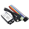
- 24 MHz 8-channel USB logic analyzer - captures SDA/SCL waveforms so PulseView can decode I2C traffic
- 10-pin logic analyzer test hook lead set (20 cm) - clips onto SDA, SCL, ground, and a marker pin without disturbing the circuit
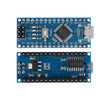
- Arduino Nano V3.0 ATmega328P (pre-soldered) - generates predictable I2C traffic and prints results over Serial
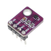
- GY-SHT45 temperature and humidity I2C sensor module - the I2C target device being decoded in PulseView
- 400-point solderless breadboard - makes it easy to probe SDA/SCL and move test points
- 22 AWG solid-core hookup wire set - short, flat links that leave room for the test hooks
- Dupont jumper wires - convenient jumpers for power and signal routing
External
- USB cables for the Nano and the analyzer
- A computer with the Arduino IDE and PulseView (free, part of the sigrok project)
- A four-channel bidirectional 3.3 V/5 V logic-level converter with pull-ups and support for I2C and ordinary digital signals, such as SparkFun BOB-12009; three channels are used here
- A multimeter to check the 3.3 V and 5 V rails before connecting the sensor
Note: Always connect the analyzer ground lead first. Without a shared ground the decoder sees noise instead of I2C.
Step-by-Step Guide
Step 1 - Wire the Nano and the SHT45
Goal: Connect the 5 V Nano to the SHT45 through a bidirectional level converter, while keeping the sensor and analyzer signals at 3.3 V.
What to do: With power disconnected, place the boards on the breadboard and use short wires. This ATmega328P Nano uses 5 V logic. Use 3.3 V for the GY-SHT45 supply and sensor-side pull-ups: Sensirion specifies a 1.08–3.6 V operating supply for the SHT4x. Do not assume a GY-SHT45 board accepts 5 V on its supply or signal pins. The SHT4x datasheet and classic Nano documentation describe these different voltage domains.
| Connection | Wiring |
|---|---|
| Common ground | Nano GND, SHT45 GND and level-converter GND together |
| 5 V side | Nano 5V → converter HV |
| 3.3 V side | Nano 3V3 → converter LV and SHT45 VIN/VCC |
| SDA | Nano A4 → HV1; LV1 → SHT45 SDA |
| SCL | Nano A5 → HV2; LV2 → SHT45 SCL |
| Marker | Nano D2 → HV3; LV3 is the 3.3 V marker test point for the analyzer |
HV1/LV1, HV2/LV2 and HV3/LV3 are three separate matching channels. Follow the pin labels and schematic of your converter, not its physical orientation in a generic photo. The example converter includes pull-ups to each side’s reference rail; check your chosen converter’s pull-up arrangement and do not add any pull-up to 5 V on the sensor side. The translation principle is documented in Nexperia AN10441; the example board’s GPIO and I2C usage is covered by SparkFun’s hookup guide.
Check the Nano’s 3V3 output and converter references with a meter before attaching the sensor. If using a Nano variant without a documented suitable 3.3 V output, use a separate regulated 3.3 V supply with common ground instead.
Expected result: The sensor has a 3.3 V supply, and SDA/SCL are translated between the Nano’s 5 V side and the sensor’s 3.3 V side. The three low-voltage test points remain accessible.
Step 2 - Upload the probe-friendly sketch
Goal: Generate predictable I2C traffic and print what the Nano received.
What to do: Upload this sketch. At start-up it reads the sensor's serial number (command 0x89). Every two seconds it then sends the high-precision measurement command 0xFD, waits 10 ms (the datasheet allows up to about 8.3 ms), reads six bytes, and checks both CRCs. D2 goes HIGH for the duration of each transaction, which gives the analyzer a clean trigger.
Code:
// ShillehTek: SHT45 on an Arduino Nano, built to be watched with a logic analyzer
// Every 2 s: marker pulse on D2, measure command 0xFD, wait 10 ms, read 6 bytes, check CRCs
#include <Wire.h>

const uint8_t SHT45_ADDR = 0x44;      // most SHT45 boards; some use 0x45 or 0x46
const uint8_t CMD_MEASURE_HIGH = 0xFD; // high-precision temperature + humidity
const uint8_t CMD_SERIAL = 0x89;       // read the 32-bit serial number
const uint8_t MARKER_PIN = 2;          // goes HIGH for the whole transaction: trigger on it

uint8_t crc8(const uint8_t *data, uint8_t len) {   // Sensirion CRC-8: poly 0x31, init 0xFF
  uint8_t crc = 0xFF;
  for (uint8_t i = 0; i < len; i++) {
    crc ^= data[i];
    for (uint8_t b = 0; b < 8; b++) {
      crc = (crc & 0x80) ? (uint8_t)((crc << 1) ^ 0x31) : (uint8_t)(crc << 1);
    }
  }
  return crc;
}

// Sends one command byte, waits, then reads 6 bytes. Returns false on NACK or short read.
bool shtCommand(uint8_t cmd, uint16_t waitMs, uint8_t *buf) {
  Wire.beginTransmission(SHT45_ADDR);
  Wire.write(cmd);
  if (Wire.endTransmission() != 0) return false;    // no ACK: wrong address or wiring
  delay(waitMs);
  if (Wire.requestFrom(SHT45_ADDR, (uint8_t)6) != 6) return false;
  for (uint8_t i = 0; i < 6; i++) buf[i] = Wire.read();
  return true;
}

void printHex(uint8_t v) {
  if (v < 0x10) Serial.print('0');
  Serial.print(v, HEX);
  Serial.print(' ');
}

void setup() {
  Serial.begin(115200);
  pinMode(MARKER_PIN, OUTPUT);
  Wire.begin();                // A4 = SDA, A5 = SCL, 100 kHz
  uint8_t b[6];
  digitalWrite(MARKER_PIN, HIGH);
  bool ok = shtCommand(CMD_SERIAL, 1, b);
  digitalWrite(MARKER_PIN, LOW);
  if (ok && crc8(b, 2) == b[2] && crc8(b + 3, 2) == b[5]) {
    Serial.print(F("SHT45 serial: "));
    printHex(b[0]); printHex(b[1]); printHex(b[3]); printHex(b[4]);
    Serial.println();
  } else {
    Serial.println(F("SHT45 not answering at 0x44 - check wiring or try 0x45"));
  }
}

void loop() {
  uint8_t b[6];
  digitalWrite(MARKER_PIN, HIGH);
  bool ok = shtCommand(CMD_MEASURE_HIGH, 10, b);   // max 8.3 ms per datasheet
  digitalWrite(MARKER_PIN, LOW);

  if (!ok) {
    Serial.println(F("Read failed (NACK)"));
  } else {
    Serial.print(F("Raw: "));
    for (uint8_t i = 0; i < 6; i++) printHex(b[i]);
    bool crcT = crc8(b, 2) == b[2];
    bool crcH = crc8(b + 3, 2) == b[5];
    uint16_t rawT = ((uint16_t)b[0] << 8) | b[1];
    uint16_t rawH = ((uint16_t)b[3] << 8) | b[4];
    float tC = -45.0f + 175.0f * rawT / 65535.0f;
    float rh = -6.0f + 125.0f * rawH / 65535.0f;
    rh = constrain(rh, 0.0f, 100.0f);
    Serial.print(F("| T "));
    Serial.print(tC, 2);
    Serial.print(F(" C  RH "));
    Serial.print(rh, 2);
    Serial.print(F(" %  CRC "));
    Serial.println(crcT && crcH ? F("OK") : F("BAD"));
  }
  delay(2000);
}
Expected result: The Serial Monitor at 115200 baud shows the serial number once, then lines such as Raw: 66 B4 F5 7C 2A 53 | T 25.21 C RH 54.63 % CRC OK every two seconds.
Step 3 - Clip on the logic analyzer
Goal: Connect three signal channels and a shared ground without exposing the sensor-side signals to 5 V.
What to do: With both devices unpowered, verify the hook harness’s connector pitch, physical fit and pin-by-pin continuity against the analyzer’s channel/GND markings. Do not assume that two 10-pin connectors have the same mapping or rely on wire colors alone. If the harness does not match, use individual compatible test leads instead. Attach the ground lead first, then use these 3.3 V points on the converter:
- Analyzer GND → circuit GND (connect this first).
- Analyzer D0 → LV1 / SHT45 SDA.
- Analyzer D1 → LV2 / SHT45 SCL.
- Analyzer D2 → LV3, the translated Nano D2 marker. Do not clip this channel directly to the Nano’s 5 V D2 pin.
All three captured signals are on the 3.3 V side. Confirm your analyzer supports 3.3 V logic inputs; this wiring does not depend on unverified 5 V input tolerance.

Expected result: The hooks grip the low-voltage test points firmly, with the ground lead attached to the circuit ground. PulseView D2 still shows the sketch’s marker pulse after translation.
Step 4 - Install PulseView and the analyzer driver
Goal: Let your computer talk to the analyzer.
What to do: Install PulseView from the sigrok website. These 24 MHz boards use the open-source fx2lafw driver, so in PulseView pick fx2lafw (generic driver for FX2 based LAs) when connecting. On Windows, run the Zadig tool once, select the analyzer in the device list, and install the WinUSB driver for it. macOS needs no extra driver; on Linux, install sigrok's udev rules if PulseView only finds the analyzer when run as root.
Expected result: PulseView shows the analyzer with channels D0 to D7 ready to capture.
Step 5 - Capture a transaction
Goal: Record exactly one measurement cycle.
What to do: The Nano runs I2C at 100 kHz, so set the sample rate to 1 MHz (ten samples per bit) and the sample count to 1 M samples, about one second. Click the D2 channel's trigger icon and choose a rising edge. Press Run: PulseView waits until the Nano raises D2, then records the transaction that follows.
Expected result: D2 shows a pulse about 11 ms wide, SCL shows two bursts of clock pulses, and SDA changes only while SCL is low, except for the start and stop conditions.
Step 6 - Decode and check the bytes by hand
Goal: Turn the waveforms into numbers and verify them.
What to do: Click the decoder button, add I²C, and assign SCL = D1 and SDA = D0. Each cycle decodes as:
- Write: Start, address 0x44 with the write bit, ACK, data 0xFD, ACK, Stop.
- About 10 ms of silence while the SHT45 converts.
- Read: Start, address 0x44 with the read bit, ACK, then six data bytes. The Nano ACKs the first five and NACKs the last to end the read, then sends Stop.
With the example bytes 66 B4 F5 7C 2A 53: temperature = −45 + 175 × 0x66B4 / 65535 = −45 + 175 × 26292 / 65535 ≈ 25.21 °C, and humidity = −6 + 125 × 0x7C2A / 65535 = −6 + 125 × 31786 / 65535 ≈ 54.63 %. Bytes F5 and 53 are the CRC-8 checksums (polynomial 0x31, start value 0xFF) of 66 B4 and 7C 2A. A quick self-test for any CRC routine: 0xBE 0xEF must give 0x92.
Expected result: The decoded bytes in PulseView match the Raw line in the Serial Monitor, and your hand calculation matches the printed temperature and humidity.
Step 7 - Use it to find real faults
Goal: Recognize common I2C problems on sight.
What to do: Try each fault on purpose and watch the capture:
-
Wrong address: change
SHT45_ADDRto 0x45. The decoder shows a NACK right after the address byte and the sketch prints "Read failed (NACK)". - Reading too early: lower the 10 ms wait to 2 ms. The read address is NACKed because the sensor is still converting.
- Pull-up problems: Check that each I2C side has pull-ups to its own reference voltage. A missing or overly weak pull-up can produce slow rising edges or missing bits. Do not move a sensor-side pull-up to 5 V to create a fault.
- Loose ground lead: random edges and garbage decodes appear even though the Serial Monitor shows good data.
Expected result: You can match each symptom in PulseView to its cause, which is the fastest way to debug any I2C, SPI, or UART device later.
Conclusion
You used a 24 MHz USB logic analyzer and a test hook lead set to capture an Arduino Nano reading an SHT45 over I2C, decoded the bus in PulseView, and checked the temperature, humidity, and CRC bytes by hand. The same trigger-on-a-marker trick works for any bus you need to debug.
Want the exact parts used in this build? Grab them from ShillehTek.com. If you want help customizing this project or building something for your product, check out our IoT consulting services.
Credits
All photos and images in this tutorial are credited to Moritz Strube on Hackster.io (MIT license). The original guide by Moritz Strube served as the reference for this ShillehTek version. We thank them for their excellent work in the maker community.